Emissions and engine control systems
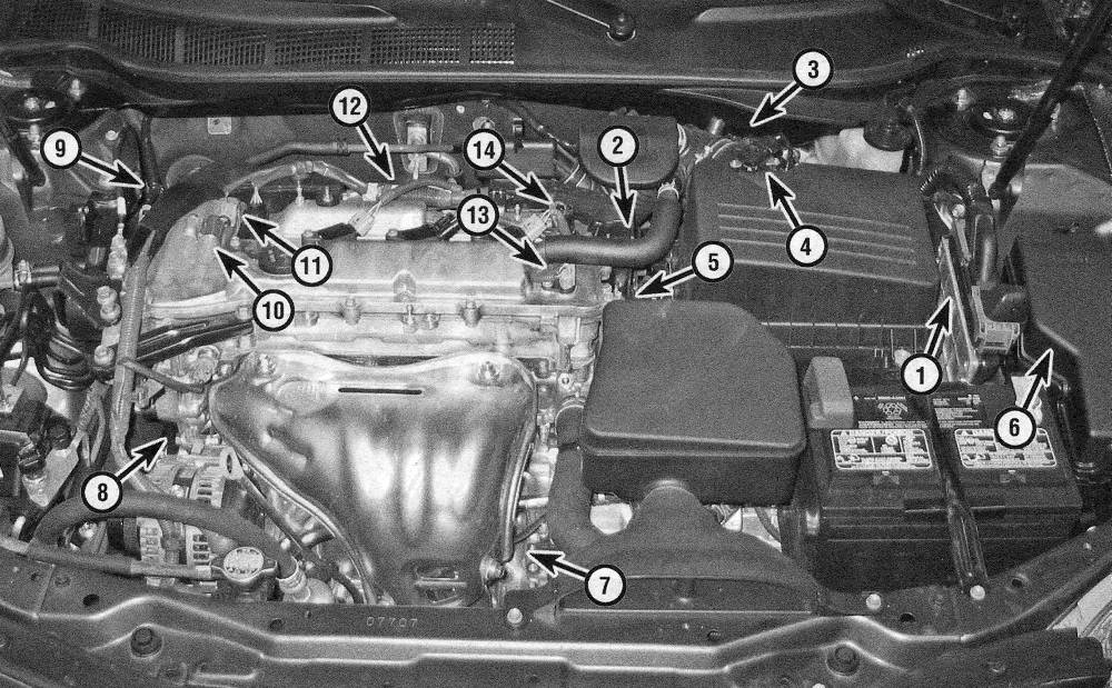
Emissions and engine control system components — 2010 and later four-cylinder models
1 Powertrain Control Module (PCM)
2 Throttle body
3 Canister Purge Vacuum Switching Valve (VSV)
4 Mass Air Flow (MAF) sensor
5 Engine Coolant Temperature (ECT) sensor
6 Engine compartment fuse and relay box
7 Oxygen sensor/Air-fuel ratio sensor (bank 1, sensor 1)
8 Crankshaft Position (CKP) sensor
9 Vacuum Switching Valve (VSV) for ACIS
10 Camshaft Oil Control Valve assembly (exhaust camshaft)
11 Camshaft Oil Control Valve assembly (intake camshaft)
12 Knock sensors (located underneath the intake manifold)
13 Camshaft Position (CMP) sensor (exhaust side)
14 Camshaft Position (CMP) sensor (intake side)
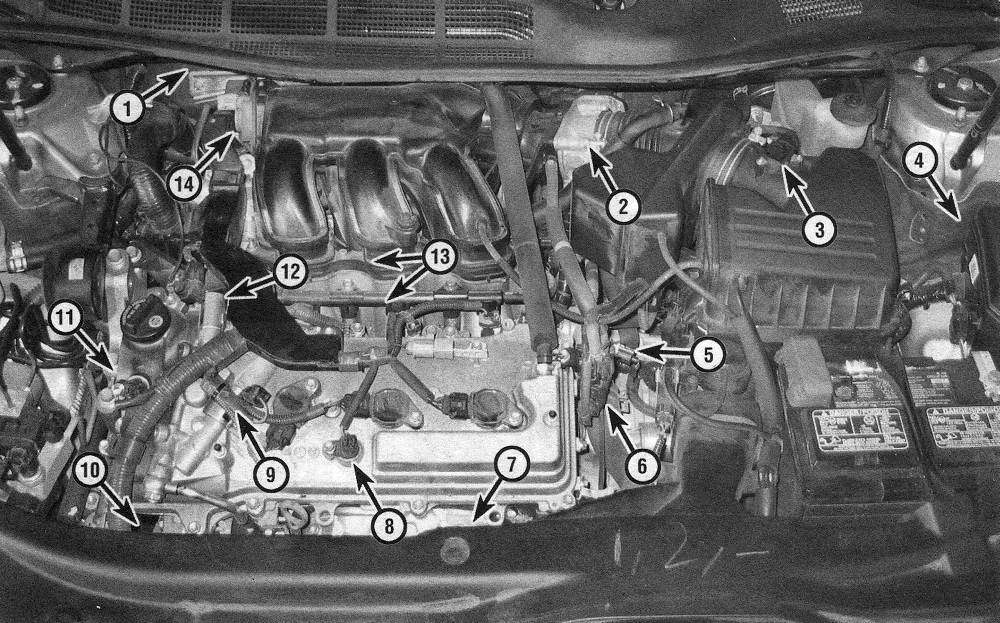
Emissions and engine control system components — 2010 and later four-cylinder models
1 Powertrain Control Module (PCM)
2 Throttle body
3 Mass Air Flow (MAF) sensor
4 Engine compartment fuse and relay box
5 Engine Coolant Temperature (ECT) sensor
6 Canister Purge Vacuum Switching Valve (VSV)
7 Oxygen sensor/Air-fuel ratio sensor (bank 2, sensor 1)
8 Variable Valve Timing sensor (VVT) for the exhaust camshaft (bank 2)
9 Camshaft Timing Oil Control Valve assembly (bank 2, exhaust side)
10 Crankshaft Position (CKP) sensor
11 Variable Valve Timing sensor (VVT) for the intake camshaft (bank 2)
12 Camshaft Timing Oil Control Valve assembly (bank 2, intake side)
13 Knock sensors (located underneath the intake manifold)
14 ACTS actuator
1. To prevent pollution of the atmosphere from incompletely burned and evaporating gases, and to maintain good driveability and fuel economy, a number of emission control systems are incorporated. They include the:
Catalytic converter
2. A catalytic converter is an emission control device in the exhaust system that reduces certain pollutants in the exhaust gas stream. There are two types of converters: oxidation converters and reduction converters.
3. Oxidation converters contain a monolithic substrate (a ceramic honeycomb) coated with the semi-precious metals platinum and palladium. An oxidation catalyst reduces unburned hydrocarbons (HC) and carbon monoxide (CO) by adding oxygen to the exhaust stream as it passes through the substrate, which, in the presence of high temperature and the catalyst materials, converts the HC and CO to water vapor (H2O) and carbon dioxide (CO2).
4. Reduction converters contain a monolithic substrate coated with platinum and rhodium. A reduction catalyst reduces oxides of nitrogen (NOx) by removing oxygen, which in the presence of high temperature and the catalyst material produces nitrogen (N) and carbon dioxide (002).
5. Catalytic converters that combine both types of catalysts in one assembly are known as «three-way catalysts» or TWCs. A TWC can reduce all three pollutants.
Evaporative Emissions Control (EVAP) system
6. The Evaporative Emissions Control (EVAP) system prevents fuel system vapors (which contain unburned hydrocarbons) from escaping into the atmosphere. On warm days, vapors trapped inside the fuel tank expand until the pressure reaches a certain threshold. Then the fuel vapors are routed from the fuel tank through the fuel vapor vent valve and the fuel vapor control valve to the EVAP canister, where they’re stored temporarily until the next time the vehicle is operated. When the conditions are right (engine warmed up, vehicle up to speed, moderate or heavy load on the engine, etc.) the PCM opens the canister purge valve, which allows fuel vapors to be drawn from the canister into the intake manifold. Once in the intake manifold, the fuel vapors mix with incoming air before being drawn through the intake ports into the combustion chambers where they’re burned up with the rest of the air/fuel mixture. The EVAP system is complex and virtually impossible to troubleshoot without the right tools and training.
Exhaust Gas Recirculation (EGR) system
7. The EGR system reduces oxides of nitrogen by recirculating exhaust gases from the exhaust manifold, through the EGR valve and intake manifold, then back to the combustion chambers, where it mixes with the incoming air/fuel mixture before being consumed. These recirculated exhaust gases dilute the incoming air/fuel mixture, which cools the combustion chambers, thereby reducing NOx emissions.
8. The EGR system consists of the Powertrain Control Module (PCM), the EGR valve, the EGR valve position sensor and various other information sensors that the PCM uses to determine when to open the EGR valve. The degree to which the EGR valve is opened is referred to as «EGR valve lift.» The PCM is programmed to produce the ideal EGR valve lift for varying operating conditions. The EGR valve position sensor, which is an integral part of the EGR valve, detects the amount of EGR valve lift and sends this information to the PCM. The PCM then compares it with the appropriate EGR valve lift for the operating conditions. The PCM increases current flow to the EGR valve to increase valve lift and reduces the current to reduce the amount of lift. If EGR flow is inappropriate to the operating conditions (idle, cold engine, etc.) the PCM simply cuts the current to the EGR valve and the valve closes.
Secondary Air Injection (AIR) system
9. Some models are equipped with a secondary air injection (AIR) system. The secondary air injection system is used to reduce tailpipe emissions on initial engine start-up. The system uses an electric motor/pump assembly, relay, vacuum valve/solenoid, air shut-off valve, check valves and tubing to inject fresh air directly into the exhaust manifolds. The fresh air (oxygen) reacts with the exhaust gas in the catalytic converter to reduce HC and CO levels. The air pump and solenoid are controlled by the PCM through the AIR relay. During initial start-up, the PCM energizes the AIR relay, the relay supplies battery voltage to the air pump and the vacuum valve/solenoid, engine vacuum is applied to the air shut-off valve which opens and allows air to flow through the tubing into the exhaust manifolds. The PCM will operate the air pump until closed loop operation is reached (approximately four minutes). During normal operation, the check valves prevent exhaust backflow into the system.
Powertrain Control Module (PCM)
10. The Powertrain Control Module (PCM) is the brain of the engine management system. It also controls a wide variety of other vehicle systems. In order to program the new PCM, the dealer needs the vehicle as well as the new PCM. If you’re planning to replace the PCM with a new one, there is no point in trying to do so at home because you won’t be able to program it yourself.
Positive Crankcase Ventilation (PCV) system
11. The Positive Crankcase Ventilation (PCV) system reduces hydrocarbon emissions by scavenging crankcase vapors, which are rich in unburned hydrocarbons. A PCV valve or orifice regulates the flow of gases into the intake manifold in proportion to the amount of intake vacuum available.
12. The PCV system generally consists of the fresh air inlet hose, the PCV valve or orifice and the crankcase ventilation hose (or PCV hose). The fresh air inlet hose connects the air intake duct to a pipe on the valve cover. The crankcase ventilation hose (or PCV hose) connects the PCV valve or orifice in the valve cover to the intake manifold.