Variable Valve Timing-intelligent system — description and component replacement
Description
1. There are two types of system: a Variable Valve Timing-intelligent (VVT-i) system used on 2009 and earlier four-cylinder models and the dual Variable Valve Timing-intelligent (VVT-i) system used on all V6 models and 2010 and later four-cylinder models.
2. The VVT-I system varies intake and exhaust (if equipped) camshaft timing to produce valve timing that is optimized for the driving conditions. The VVT-i system achieves this by using engine oil pressure to advance or retard the controller on the front end of each intake camshaft(s) and exhaust camshaft(s) on all V6 models and 2010 and later four-cylinder models.
- ) 2009 and earlier four-cylinder models: 40 degrees (intake and exhaust)
- ) 2010 and later four-cylinder models: 50 degrees (intake camshaft); 40 degrees (exhaust camshaft)
- ) V6 models: 40 degrees (intake camshaft); 35 degrees (exhaust camshaft)
3. The VVT-i system on the 2009 and earlier four-cylinder models consists of a CMP sensor, CKP sensor, camshaft timing oil control valve, Electronic Control Module (ECM) and one controller (intake camshaft sprocket/actuator assembly). The dual VVT-i system on 2010 and later four-cylinder models consists of two CMP sensors, a CKP sensor, two camshaft timing oil control valves, Electronic Control Module (ECM) and two controllers (intake and exhaust camshaft sprocket/actuator assemblies). The dual VVT-I system on V6 models consists of four VVT sensors, a CKP sensor, four camshaft timing oil control valves, Electronic Control Module (ECM) and four controllers (two intake and two exhaust camshaft sprocket/ actuator assemblies). The VVT-i systems on V6 and four-cylinder models are virtually identical except for the design of the oil control valves.
4. Each controller consists of a timing rotor (for the VVT-i sensor), a housing with an impeller-type vane inside it, a lock pin and the actual timing chain sprocket for the intake camshaft. The vane is fixed on the end of the camshaft.
5. The camshaft timing oil control valve is an ECM-controlled device that controls and directs the flow of oil to the advance or retard passages leading to the controller. There is one oil control valve for each camshaft. A spring-loaded spool valve inside the oil control valve directs oil pumped into the valve toward either the advance outlet or the retard outlet port, depending on the engine condition.
Component replacement WT sensors (V6 engines only)
Warning: Wait until the engine is completely cool before beginning this procedure.
6. Disconnect the cable from the negative battery terminal (see Engine electrical systems).
7. Remove the cowl assembly (see Body).
8. Refer to Chapter V6 engine and remove the upper intake manifold for access to the two rear VVT sensors. The two front sensors can be accessed by removing the engine cover.
9. Disconnect the electrical connector from
the sensor being replaced (see illustration).
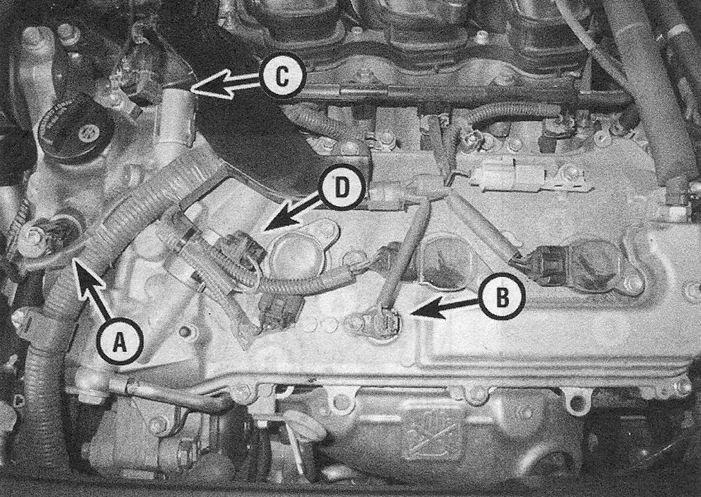
20.9 WT sensor and camshaft timing oil control valve locations (Bank 2) — V6 models
A Bank 2 Intake sensor
B Bank 2 Exhaust sensor
C Bank 2 Intake timing oil control valve
D Bank 2 Exhaust timing oil control valve
10. Remove the VVT sensor mounting bolt and remove the sensor.
11. Installation is the reverse of removal.
Camshaft timing oil control valve (s)
Note: 2009 and earlier four-cylinder models use only one camshaft timing control valve. 2010 and later four-cylinder models use two control valves. All V6 engines use four timing oil control valves.
12. Disconnect the cable from the negative battery terminal (see Engine electrical systems).
13. Remove the engine cover (s).
14. On V6 engines, refer to Chapter V6 engine and remove the upper intake manifold for access to the rear two camshaft timing oil control valves (see illustration 20.9).
15. Disconnect the electrical connector from the camshaft timing oil control valve (see illustration). On four-cylinder models, remove the engine harness mounting fasteners and move the harness to the side.
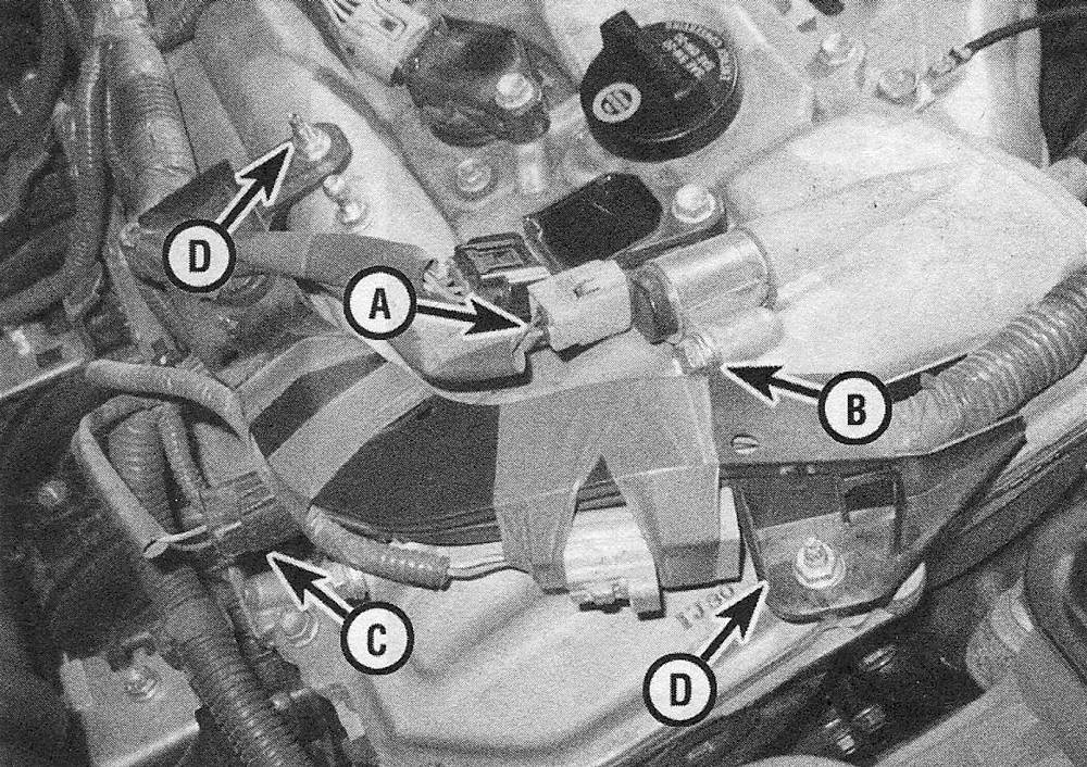
20.15 Camshaft timing oil control valve details — 2010 four-cylinder model shown
A Exhaust side camshaft timing oil control valve
B Camshaft timing oil control valve mounting bolt
C Intake side camshaft timing oil control valve
D Engine harness mounting fasteners
16. Remove the camshaft timing oil control valve mounting bolt and remove the oil control valve from the valve cover.
17. Installation is the reverse of removal.