Repair initialization
1. When certain parts are replaced or serviced, the system that controls or monitors those parts must be initialized before the vehicle is returned to service. During initialization, controllers relearn particular settings so they can effectively operate the parts in question. To initialize a particular system, find that system in this section, locate the replaced part (s) and/or the problem that was repaired, and perform the indicated procedure.
Note: On 2012 and later models, electrical power is turned on or off by either an ignition switch or an engine switch. Once initialization has started, do not turn off the ignition switch or the engine switch until initialization has been completed. Doing so interrupts the process. You will have to start again.
Power Window Control System Initialization
2. The power window control system must be initialized whenever a door window regulator assembly, power window regulator motor, door glass, or door-glass run has been replaced or reinstalled.
3. A diagnostic trouble code is set when- ever a power window regulator motor has been replaced. Clear the DTC after initialization is completed.
4. During initialization, use the power window switch of each door to initialize each power window.
5. Park the vehicle on a level surface, and turn off all electrical systems before beginning initialization.
Power window regulator motor replacement or when the window glass unexpectedly reverses or stops
6. Connect the battery, and turn on the ignition switch or the engine switch.
7. Completely open the window by pressing and holding the multiplex network master switch, power window regulator switch or the rear power window regulator switch. Continue to hold the switch for at least 1 second after the window has completely opened.
8. Completely close the window by lifting and holding the multiplex network master switch, power window regulator switch or the rear power window regulator switch. Continue to hold the switch for at least 1 second after the window has completely closed. This resets the glass position and completes initialization for the first door. Repeat for each of the remaining doors.
Power window regulator motor removal/installation; door glass or glass run removal/ installation or replacement
9. Connect the battery, and turn on the ignition switch or the engine switch.
10. Completely close the window by lifting and holding the multiplex network master switch, power window regulator switch or the rear power window regulator switch. Continue to hold the switch for at least 6 seconds after the window has completely closed.
11. Completely open the window by pressing and holding the multiplex network master switch, power window regulator switch or the rear power window regulator switch. Continue to hold the switch for at least 1 second after the window has completely opened.
12. Release the multiplex network master switch, power window regulator switch or the rear power window regulator switch, and then press and hold the switch down for 4 seconds or more.
13. Completely close the window by lifting and holding the multiplex network master switch, power window regulator switch or the rear power window regulator switch. Continue to hold the switch for at least 1 second after the window has completely closed. This resets the glass position and completes initialization for the first door. Repeat for each remaining door.
Sunroof ECU Initialization
14. The sunroof ECU must be initialized whenever the roof glass or roof drive cable subassembly is adjusted or removed and installed, or when the sliding roof drive gear is replaced.
Auto slide open and close/tilt up and down functions
do not operate
15. Turn on the ignition switch or the engine switch.
All 2012 and later models except 2013 and later ES350 models with a glass roof
16. Completely close the roof, and release the roof switch.
17. Press and hold the close or up switch. The roof should tilt up, pause for 1 second, tilt down, slide open and then slide closed. Once the system completes this operation, release the switch. The initialization is completed.
18. Confirm that the sliding roof auto function works normally.
2013 and later ES350 models with a glass roof
19. Press and hold the close or down switch. The roof should slide to its fully closed position.
20. Continue to hold the close or down switch, and confirm that the roof opens and stops again at the fully closed position. Release the close or down switch. The initialization is completed.
21. Confirm that the sliding roof auto function works properly.
If the roof automatically moves but does not stop at the correct position or the
roof reverses direction
during tilt down operation
22. Turn the on-ignition switch or the engine switch.
All 2012 and later models except 2013 and later ES350 models with a glass roof
23. Press and hold the up switch until the roof slides to the fully tilted up position and release the switch.
24. Again press the hold the up switch. The roof should pause for approximately 10 seconds or more, tilt inching motion, pause for 1 second, tilt down, slide open and then slide to the closed position. Release the up switch. The initialization is completed.
25. Confirm that the sliding roof auto function works properly.
2013 and later ES350 models with a glass roof
26. Press and hold the close or down switch. The roof should tilt down, move in the reverse direction, pause for approximately 10 seconds or more, tilt down, and stop at its fully closed position.
27. Continue to hold the close or down switch, and confirm that the roof opens and stops again at the fully closed position. Release the close or down switch. The initialization process is completed.
28. Confirm that the sliding roof auto function works properly.
The roof automatically moves, but reverses direction during the close operation
29. Turn on the ignition switch or the engine switch.
All 2012 and later models except 2013 and later ES350 models with a glass roof
30. Press and hold the close switch until the roof slides closed, moves in the reverse direction, pauses for approximately 10 seconds or more, slides closed, tilts up, pauses for 1 second, tilts down, slides open and finally slides fully closed. Release the close switch. The initialization process is completed.
31. Confirm that the sliding roof auto function works properly.
2013 and later ES350 models with a glass roof
32. Press and hold the down switch. When the roof stops sliding, release the switch.
33. Press and hold the down switch. The roof pauses for approximately 10 seconds or more and then stops at the fully closed position. Once the roof stops, confirm that the roof move again and stops at the fully closed position. The initialization process is completed.
34. Confirm that the sliding roof auto function works properly.
Drive parts or roof glass removed and installed or replaced (2012 ES350 models)
35. When replacing the sliding roof drive gear, initialize the roof ECU by turning the engine switch On and performing Steps 19 through 21.
36. When replacing drive parts and the roof glass without replacing the sliding roof drive gear and the sliding roof glass works automatically, initialize the roof ECU by turning the engine switch on and performing Steps 26 through 28. If the glass does not work automatically, perform the Steps 19 through 21.
Headlight leveling ECU (All 2012 and later Camry models and 2013 and later Avalon and ES350 models)
37. Initialize the headlight leveling ECU whenever the headlight leveling ECU assembly has been replaced, after the vehicle height has changed due to replacement or service of suspension components, and after the removal/installation or replacement of the rear height control sensor subassembly.
Pre -initialization preparation
38. Unload the vehicle and the trunk. Make sure no one is in the vehicle, and confirm that the spare tire, jack and tools are in their original positions in the trunk.
39. Park the vehicle on a level surface and confirm that the headlights are turned off.
40. Turn on the ignition switch or the engine switch, and check the headlight leveling system indicator light.
- ) If the headlight leveling ECU assembly has been replaced, the indicator light should repeatedly flash 6 times at a rate of 2 cycles per second.
- ) If the rear height control sensor subassembly has been serviced or replaced or if a suspension part has been replaced, the indicator light should turn on for approximately 3 seconds and then turn off.
41. Also note the position of the needle on the fuel gauge. During initialization, you must turn the light switch on and off a certain number of times. The position of the fuel gauge needle determines that number. If the needle indicates less than empty, turn the light switch on and off once during initialization. If the needle sits between empty and 1/4 full, cycle the switch on and off twice; if the needle sits between 1/4 and 1/2 full, cycle the switch on and off 3 times; cycle the switch 4 times if the needle sits between 1/2 and % full, and cycle the light switch on and off 5 times if the needle sits between % full and full.
Initialization
42. Use a jumper wire to connect terminals 4 (CG) and 8 (LVL) of the data link connector (DLC3).
43. While standing outside the vehicle, use the light switch to turn the low beams on and off the number of times indicated by the fuel gauge needle (see Step 41). Start within 20 seconds after connecting the data link terminals, and cycle the switch on and off at less than 3 second intervals.
44. Check the headlight leveling system indicator light. If the headlight leveling ECU assembly has been replaced, the indicator light should repeatedly flash 6 times at a rate of 2 cycles per second and then repeatedly flash the same number of times that the low beam switch was cycled on and off. If the rear height control sensor subassembly has been serviced or replaced or if vehicle height has changed because a suspension part was replaced, the indicator light should remain off and then repeatedly flash the same number of times that the low beam switch was cycled on and off.
45. Initialization is completed.
Steering lock ECU (2012 ES350 models)
46. On 2012 ES350 models with a smart access system and also a push-button start function, the starter may not operate after the battery has been charged or if the vehicle was jump-started. If either has occurred, initialize the steering lock ECU by performing the following.
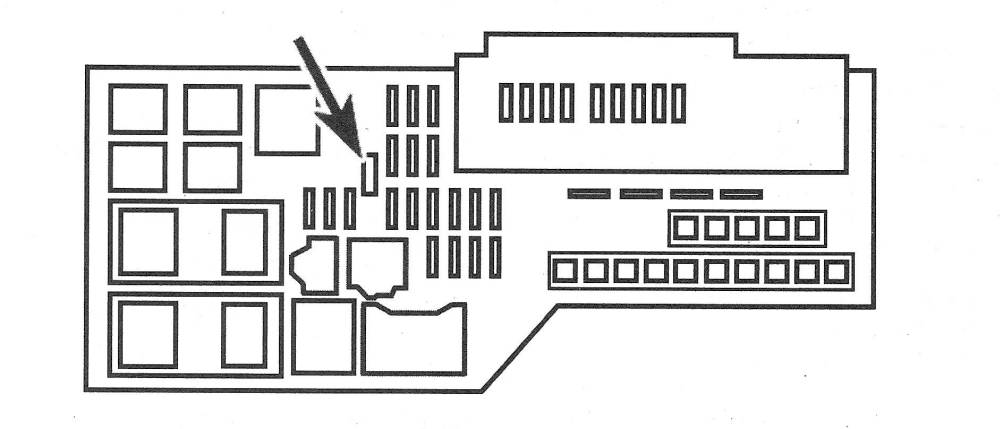
47. Confirm that the short-pin fuse has been installed in the engine compartment fuse/ relay box (see illustration). If it is not, install it now.
9.47 Short-pin fuse location (2012 ES350 models)
48. Move the shift lever to the P position, turn the engine switch Off, and open the driver’s door. The initialization process has begun.
49. Press the brake pedal, and press the start/stop switch.
50. Initialization is completed.