Camshafts and lifters — removal, inspection and installation
Note: The camshafts should be thoroughly inspected before installation and camshaft endplay should be checked prior to camshaft removal (see Step 20).
Removal
1. Disconnect the cable from the negative battery terminal (see Engine electrical systems).
2. Remove the valve cover (see Valve cover — removal and installation).
3. Place the engine at TDC on the compression stroke for number 1 cylinder (see Top Dead Center (TDC) for number one piston — locating).
4. With the engine set to TDC on the compression stroke for number 1 cylinder, apply a dab of paint to the timing chain links where they meet the timing marks on the camshaft sprockets.
5. Using a wrench to hold the camshafts from turning, loosen the camshaft sprocket bolts several turns.
6. On 2009 and earlier models, remove the timing chain tensioner from the timing chain cover and the camshaft position sensor from the cylinder head (see Emissions and engine control systems). On 2010 and later models, remove the timing chain cover and tensioner (see Timing chain and sprockets — removal, inspection and installation, Steps 19 through 25).
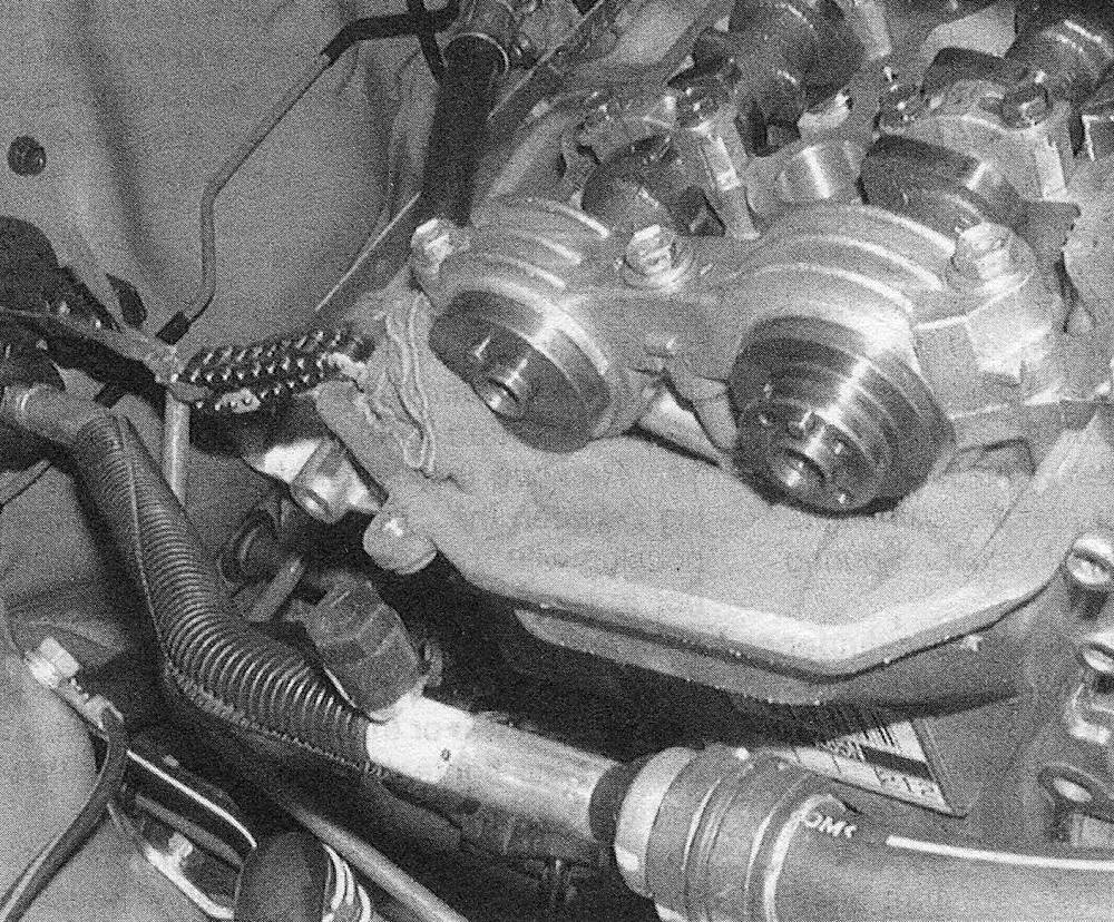
7. Remove the camshaft sprocket retaining bolts. Disengage the timing chain from the sprockets and remove the camshaft sprockets from the engine. Make sure to note that the Variable Valve Timing (VVT) actuator is installed on the intake camshaft on all models (and the exhaust camshaft on 2010 and later models). On 2009 and earlier models, after removing the sprockets, hang the timing chain up with a piece of wire and attach it to an object on the firewall (see illustration). This will prevent the timing chain from falling into the engine as the remaining steps in this procedure are performed. Also place a rag into the opening of the timing chain cover to prevent any foreign objects from falling into the engine.
7.7 With the camshaft sprockets removed, hang the timing chain out of the way with a piece of wire and place a shop rag in the timing chain cover opening to prevent foreign objects from falling into the engine
2009 and earlier models
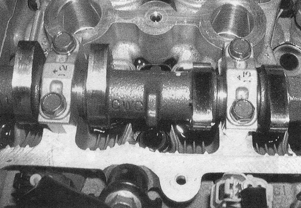
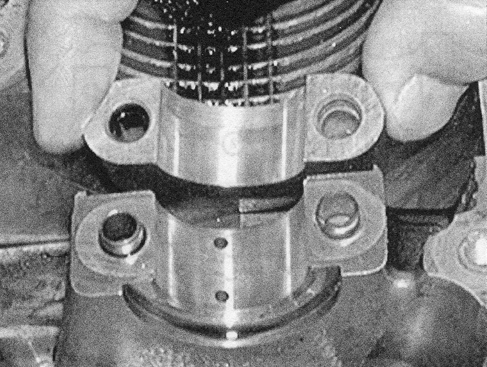
8. Verify the markings on the camshaft bearing caps. The caps should be marked from 1 to 5 with an «I» or an «E» mark on the cap indicating whether they’re for the intake or exhaust camshaft (see illustration).
7.8 The camshaft bearing caps are numbered and have an arrow that should face the timing chain end of the engine
9. Loosen the camshaft bearing caps in two or three steps, in the reverse order of the tightening sequence (see illustration 7.29). Caution: Keep the caps in order. They must go back in the same location they were removed from.
10. Detach the bearing caps, then remove the camshaft (s) from the cylinder head. Mark the camshaft(s) «Intake» or «Exhaust» to avoid mixing them up. Note: When looking at the engine from the front of the vehicle, the forward facing cam is the exhaust camshaft and the cam nearest the firewall is the intake camshaft. It is very important that the camshafts are returned to their original locations during installation.
11. Remove the lifters from the cylinder head, keeping them in order with their respective valve and cylinder (see illustrations).
7.11a Mark the lifters (I for intake, E for exhaust, and number their
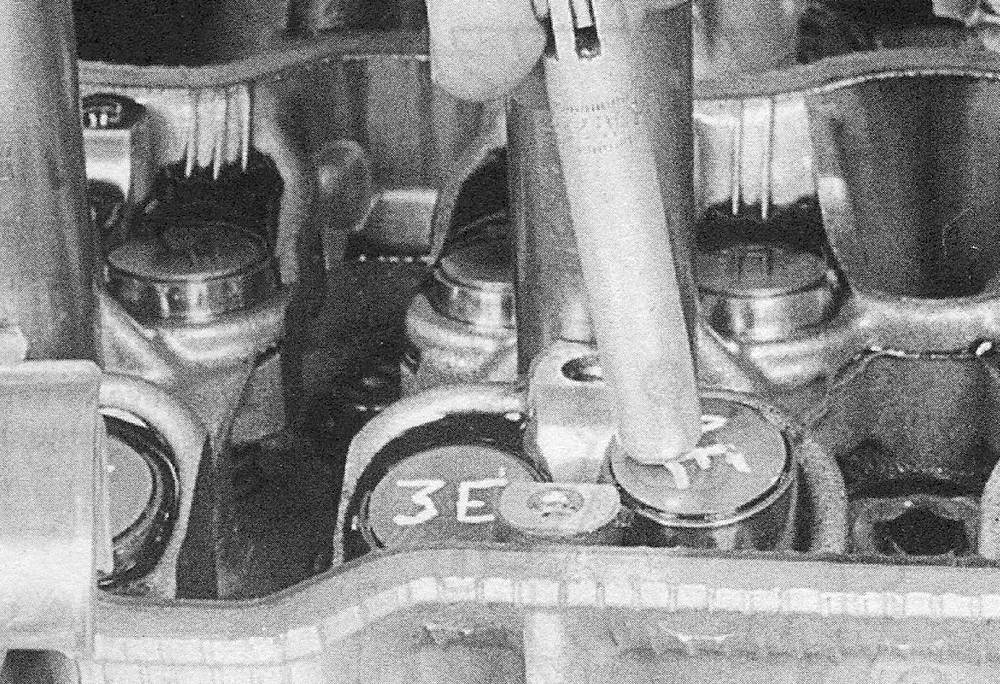
7.11b Mark up a cardboard box to store the lifters and bearing caps in order
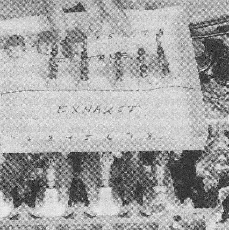
Caution: Keep the lifters in order. They must go back in the position from which they were removed.
12. Inspect the camshafts, camshaft bearings and lifters (see Steps 20 through 26). Also inspect the camshaft sprockets for wear on the teeth. Inspect the chains for cracks or excessive wear of the rollers, and for stretching (see Timing chain and sprockets — removal, inspection and installation). If any of the components show signs of excessive wear, they must be replaced.
2010 and later models
13. Loosen the camshaft housing bearing cap bolts in sequence in two or three steps, in the reverse order of the tightening sequence (see illustration 7.38).
14. Remove the camshaft housing by prying between the cylinder head and camshaft housing with a screwdriver.
Note: Be careful not to damage the cylinder head and camshaft housing.
15. Loosen the camshaft bearing cap bolts in sequence in two or three steps, in the reverse order of the tightening sequence (see illustration 7.42).
16. Remove the bearing caps, oil control filter and camshafts from the camshaft housing.
Clean the camshaft housing mounting surface and the mating surface on the cylinder head.
17. Remove the rocker arms from the cylinder head.
Caution: Keep the rocker arms in order. They must go back in the position from which they were removed.
18. Remove the lash adjusters from the cylinder head.
Caution: Keep the lash adjusters in order. They must go back in the position from which they were removed.
19. Inspect the camshafts, camshaft bearings, camshaft housing, rockers and lash adjusters as described below. Also inspect the camshaft sprockets for wear on the teeth. Inspect the chains for cracks or excessive wear of the rollers, and for stretching (see Timing chain and sprockets — removal, inspection and installation). If any of the components show signs of excessive wear, they must be replaced.
Inspection
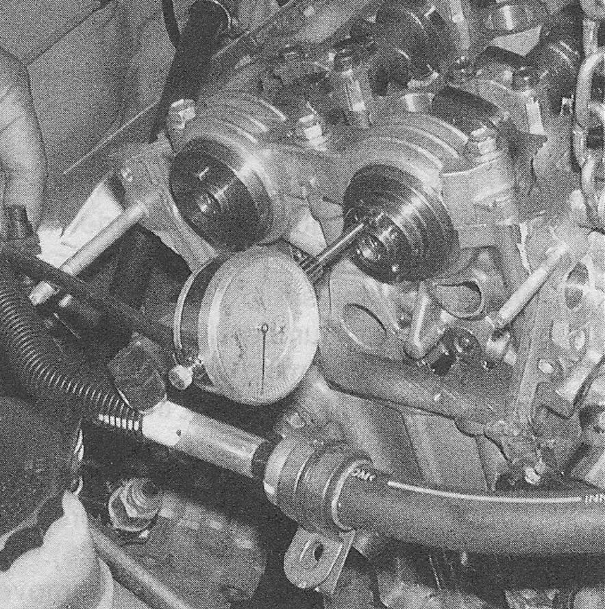
20. Before the camshafts are removed from the engine, check the camshaft endplay by placing a dial indicator with the stem in line with the camshaft and touching the snout (see illustration). Push the camshaft all the way to the rear and zero the dial indicator. Next, pry the camshaft to the front as far as possible and check the reading on the dial indicator. The distance it moves is the endplay. If the endplay for the intake camshaft is greater than the Specifications listed in this Chapter, check the thrust surfaces of the No.1 journal bearing for wear. If the thrust surface is worn, the bearings must be replaced. If the endplay for the exhaust camshaft is greater than the Specifications listed in this Chapter, the camshaft or the cylinder head (or both) may need to be replaced.
7.20 Mount a dial indicator as shown to measure camshaft endplay — pry the camshaft forward and back and read the endplay on the dial
21. With the camshafts removed, visually check the camshaft bearing surfaces in the cylinder head for pitting, score marks, galling and abnormal wear. On 2009 and earlier models, if the bearing surfaces are damaged, the der head or the No.1 journal bearings of the intake camshaft may have to be replaced (see illustration) On 2010 and later models, the camshaft housing or camshaft(s) will need to be replaced.
7.21 Inspect the No. 2 through No. 5 cam bearing surfaces in the cylinder head for pits, score marks and abnormal wear — if wear or damage is noted, the cylinder head (2009 and earlier models) or the camshaft housing (2010 and later models) must be replaced
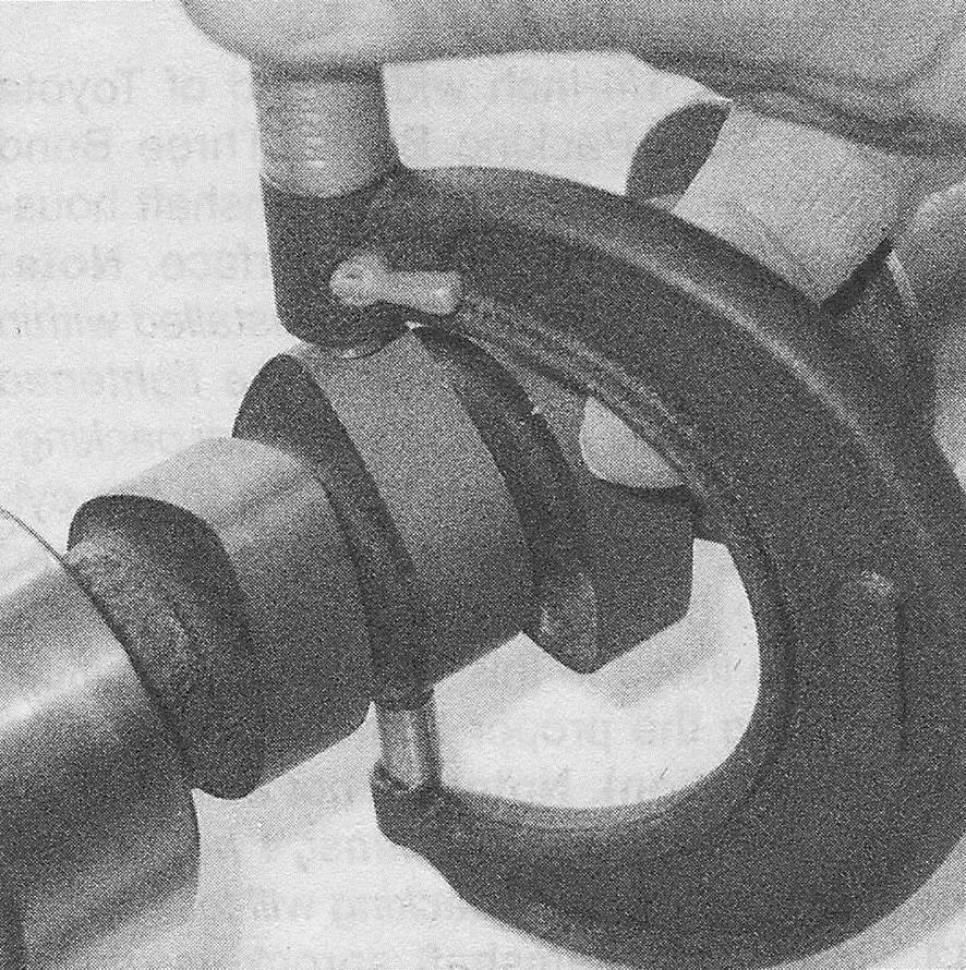
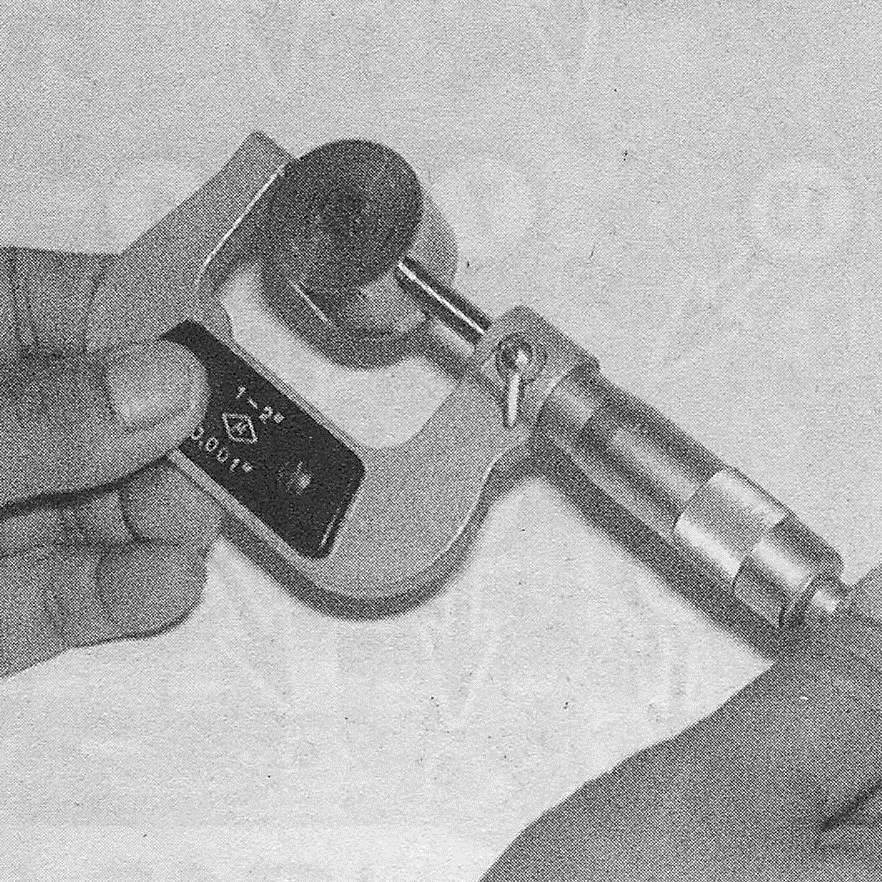
22. Measure the outside diameter of each camshaft bearing journal and record your measurements (see illustration). Compare them to the journal outside diameter specified in this Chapter, then measure the inside diameter of each corresponding camshaft bearing and record the measurements. Subtract each cam journal outside diameter from its respective cam bearing bore inside diameter to determine the oil clearance for each bearing. Compare the results to the specified journal to-bearing clearance. If any of the measurements fall outside the standard specified wear limits in this Chapter, either the camshaft or the cylinder head (or both) must be replaced
7.22 Measure each journal diameter with a micrometer if any journal measures less than the specified limit, replace the camshaft
Note: If precision measuring tools are not available, Pastorage may be used to determine the bearing journal oil clearance.
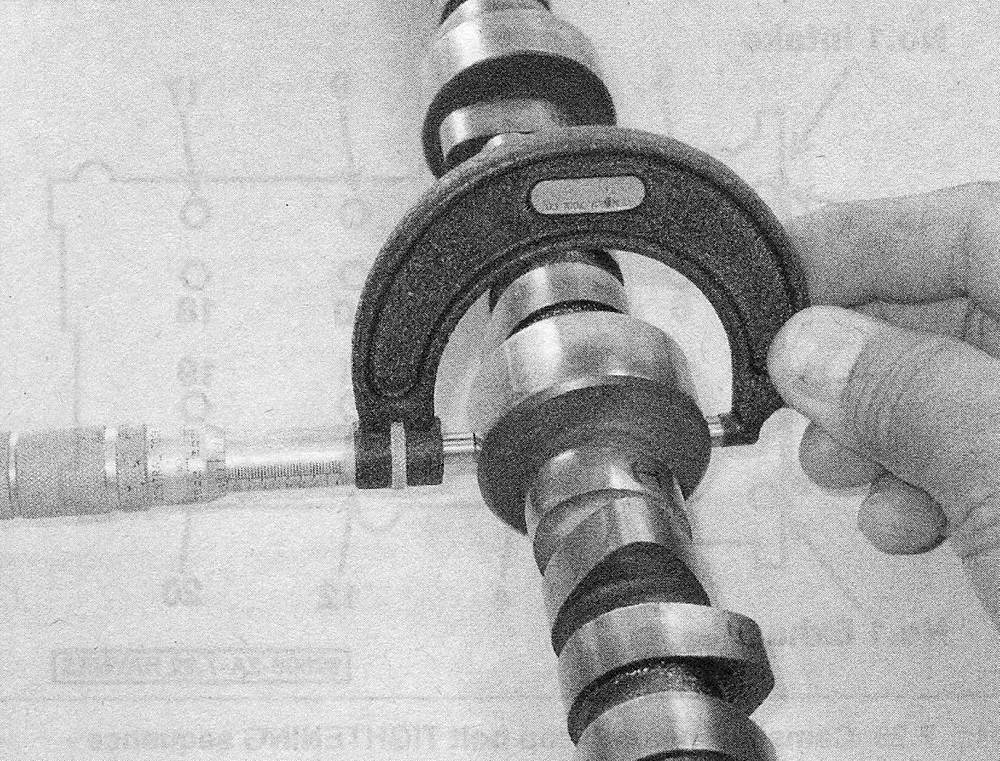
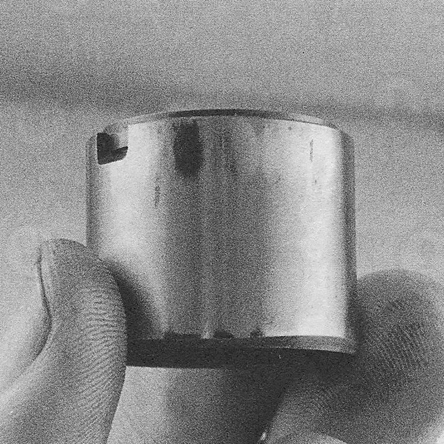
23. Using a micrometer, measure the height of each camshaft lobe (see illustration). Compare your measurements with this Chapter’s Specifications. If the height for any one lobe is less than the specified minimum, replace the camshaft.
7.23 Measure the lobe heights on each camshaft — if any lobe height is less than the specified allowable minimum, replace that camshaft
24. Check the camshaft runout by placing the camshaft back into the cylinder head and set up a dial indicator on the center journal. Zero the dial indicator. Turn the camshaft slowly and note the dial indicator readings. Runout should not exceed 0.0012 inch (0.03 mm). If the measured runout exceeds the specified runout, replace the camshaft.
25. Inspect the lifters for scuffing and score marks (see illustration). On 2010 and later models, inspect each rocker as well.
7.25 Wipe off the oil and inspect each lifter for wear and scuffing — 2009 and earlier model shown
26. Measure the outside diameter of each lifter (see illustration) and the corresponding lifter bore inside diameter. Subtract the lifter diameter from the lifter bore diameter to determine the oil clearance. Compare it to this Chapter’s Specifications. If the oil clearance is excessive, a new cylinder head and/or new lifters will be required.
7.26 Measure the outside diameter of each lifter and the inside diameter of each lifter bore to determine the oil clearance measurement (2009 and earlier models)
Installation
2009 and earlier models
27. If the No.1 journal bearings were removed, install them into the cylinder head and the bearing cap now. Apply camshaft installation lubricant to the camshaft lobes and journals and install the camshaft into the cylinder head with the No.1 cylinder camshaft lobes pointing outward away from each other (at an approximately 30-degree angle), and the dowel pins facing upward.
28. Install the bearing caps and bolts and tighten them hand tight.
29. Tighten the bearing cap bolts in several equal steps, to the torque listed in this Chapter’s Specifications, using the proper tightening sequence (see illustration).
7.29 Camshaft bearing cap bolt TIGHTENING sequence 2009 and earlier models
30. Engage the camshaft sprocket teeth with the timing chain links so that the match marks made during removal align with the upper timing marks on the sprockets, then position the sprockets over the dowels on the camshaft hubs and install the camshaft sprocket bolts finger tight. The mark on the crankshaft pulley should be aligned with the «0» mark on the timing chain cover, the camshaft sprocket TDC marks should be aligned and parallel with the top of the timing chain cover, and the timing chain match marks should be aligned with the upper timing sprocket marks with all of the slack in the chain positioned towards the tensioner side of the engine.
31. Double check that the timing sprockets are returned to the proper camshaft and tighten the camshaft sprocket bolts to the torque listed in this Chapter’s Specifications.
32. Install the timing chain tensioner as described in Section Timing chain and sprockets — removal, inspection and installation, Steps 41 and 42.
33. The remainder of installation is the reverse of removal.
2010 and later models
34. Coat the lash adjusters with engine oil and install them into the cylinder head in the same locations from which they were removed.
35. Apply oil to the rocker arms and install them, making sure each rocker arm is seated to its lash adjuster.
36. Install the camshaft bearings and oil control valve filter into the camshaft housing.
37. Apply camshaft installation lubricant to the camshaft lobes and journals and install the camshaft into the camshaft housing.
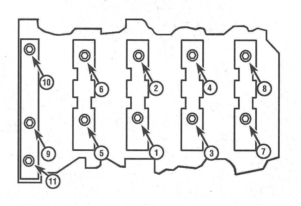
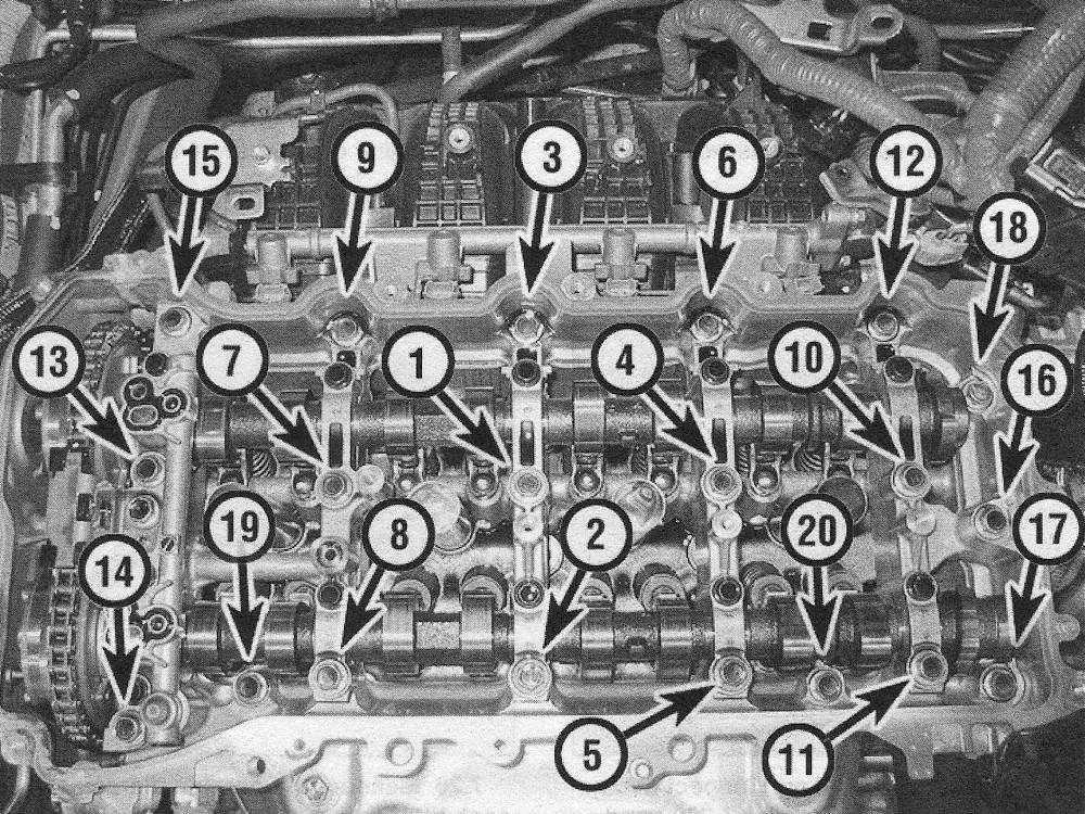
38. Install the camshaft bearing caps to the camshaft housing and tighten the bearing cap bolts in several equal steps, to the torque listed in this Chapter’s Specifications, using the proper tightening sequence (see illustration ).
7.38 Camshaft bearing cap bolt TIGHTENING sequence 2010 and later models
39. Check that the rocker arms are installed properly and have not moved.
40. Position the dowel pins facing upwards; the intake camshaft dowel pin should be at a 17-degree angle and the exhaust pin should be at a 2-degree angle (counterclockwise from the 12 o’clock position).
41. Apply a 1/4-inch-wide bead of Toyota Genuine Seal Packing Black, Three Bond 1207B (or equivalent) to the camshaft housing-to-cylinder head contact surface.
Note: The camshaft housing must be installed within 3 minutes, and the bolts must be tightened within 10 minutes after applying seal packing.
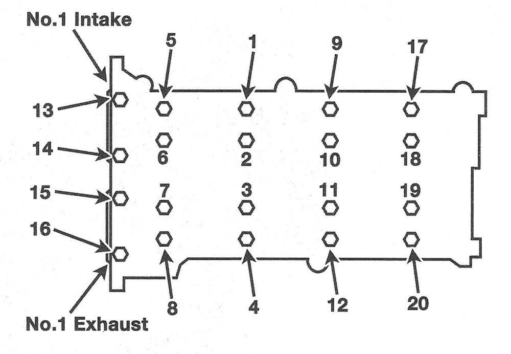
42. Install the camshaft housing to the cylinder head, install the mounting bolts and tighten the bolts in several equal steps, to the torque listed in this Chapter’s Specifications, using the proper tightening sequence (see illustration).
7.42 Camshaft housing bolt TIGHTENING sequence — 2010 and later models
Note: Do not add oil or try to start the engine for at least 4 hours after installation or the seal packing will leak.
43. Install the camshaft sprockets, timing chain and timing chain cover (see Timing chain and sprockets — removal, inspection and installation).
44. The remainder of installation is the reverse of removal.