Timing chain and sprockets — removal, inspection and installation
Note: If you’re working on a 2010 or later model, the manufacturer recommends removing the engine and transaxle assembly to perform this procedure.
Removal
Warning: Wait until the engine is completely cool before beginning this procedure.
Caution: The timing system is complex, and severe engine damage will occur if you make any mistakes. Do not attempt this procedure unless you are highly experienced with this type of repair. If you are at all unsure of your abilities, be sure to consult an expert. Double-check all your work and be sure everything is correct before you attempt to start the engine.
1. Disconnect the cable from the negative battery terminal (see Engine electrical systems).
2. Remove the drivebelt (see Tune-up and routine maintenance) and the alternator (see Engine electrical systems).
3. Remove the valve cover (see Valve cover — removal and installation) and the ABS actuator, if equipped (see Brakes).
Note: On 2010 and later models remove the three gaskets from the camshaft bearing caps.
4. With the parking brake applied and the rear wheels blocked, loosen the right front wheel lug nuts, then raise the front of the vehicle and support it securely on jack stands. Remove the right front wheel and the right splash shield from the wheel well.
5. Drain the cooling system (see Tune-up and routine maintenance).
6. While the coolant is draining, remove the power steering pump from the engine without disconnecting the fluid lines (see Suspension and steering systems). Tie the power steering pump to the body with a piece of wire and position it out of the way. link — intake 7 Position the number one piston at TDC on the compression stroke (see Top Dead Center (TDC) for number one piston — locating). Confirm the engine is at TDC on the compression stroke by verifying that the timing mark on the crankshaft pulley/vibration damper is aligned with the «0» mark on the timing chain cover and the camshaft sprocket marks are aligned with the marks on the camshaft front bearing caps (see illustrations).
Note: There are two sets of marks on the camshaft sprockets
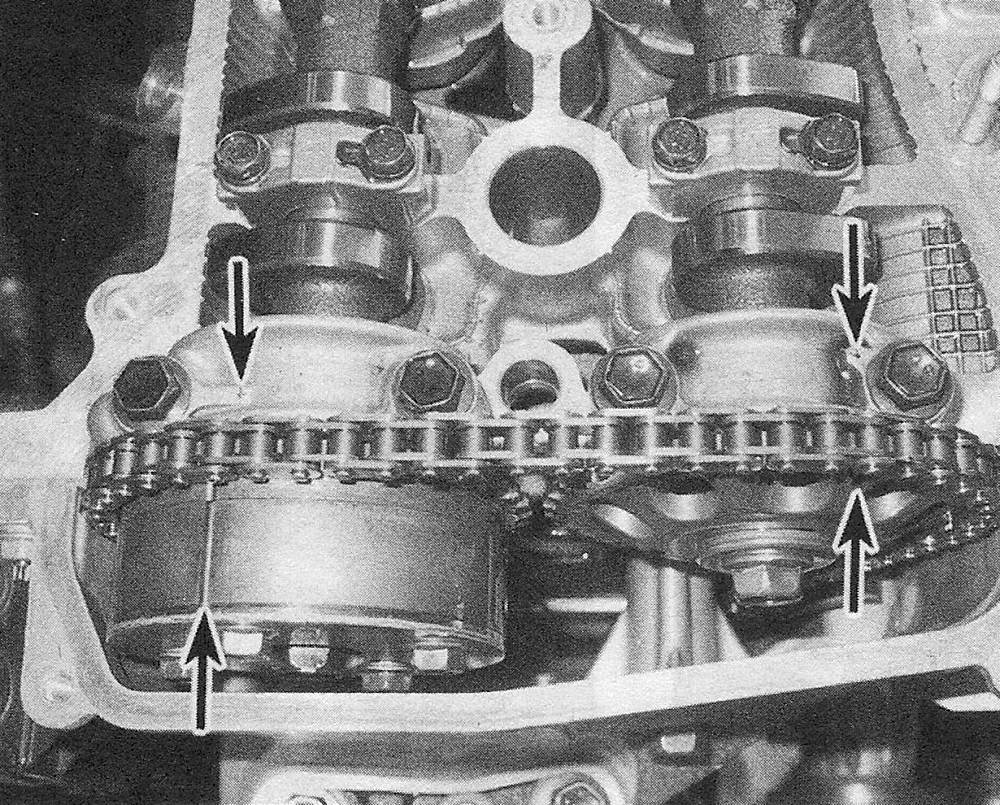
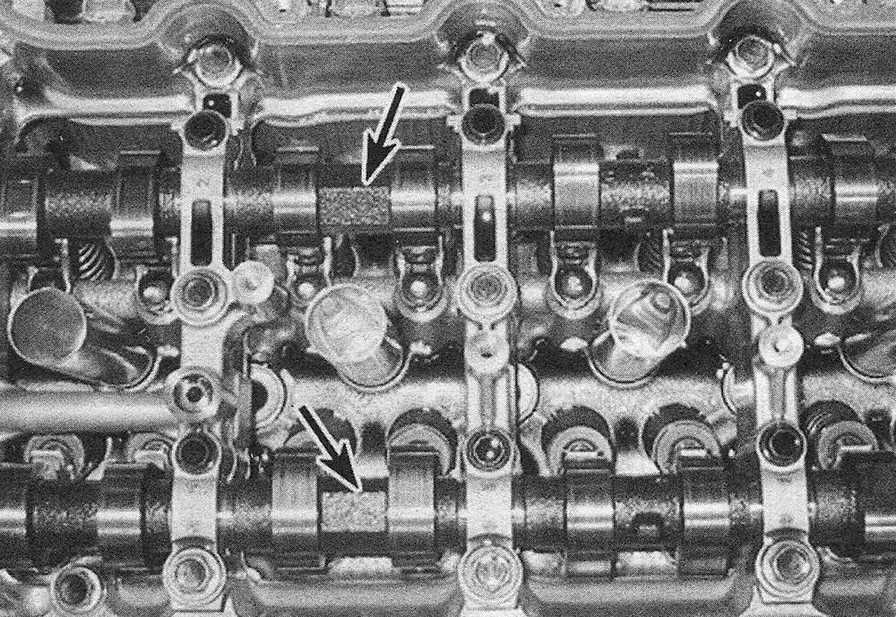
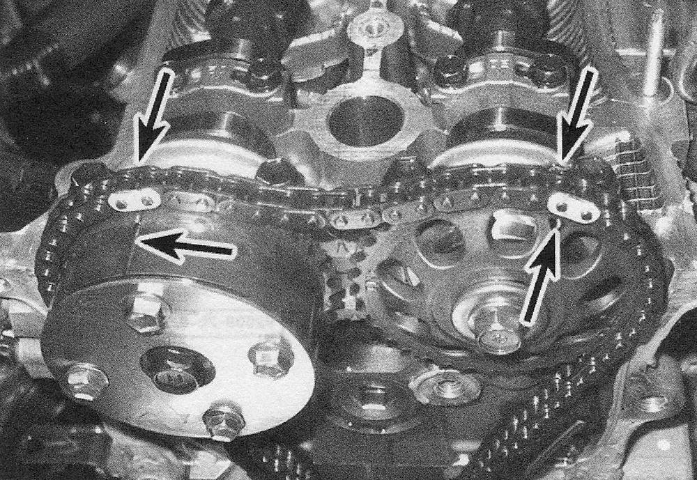
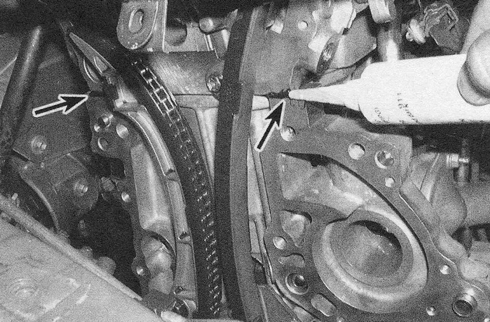
7. Position the number one piston at TDC on the compression stroke (see Top Dead Center (TDC) for number one piston — locating). Confirm the engine is at TDC on the compression stroke by verifying that the timing mark on the crankshaft pulley/vibration damper is aligned with the «0» mark on the timing chain cover and the camshaft sprocket marks are aligned with the marks on the camshaft front bearing caps (see illustrations).
Note: There are two sets of marks on the camshaft sprockets. The marks that align at TDC are for TDC reference only; the other two marks are used to align the sprockets with the timing chain during installation.
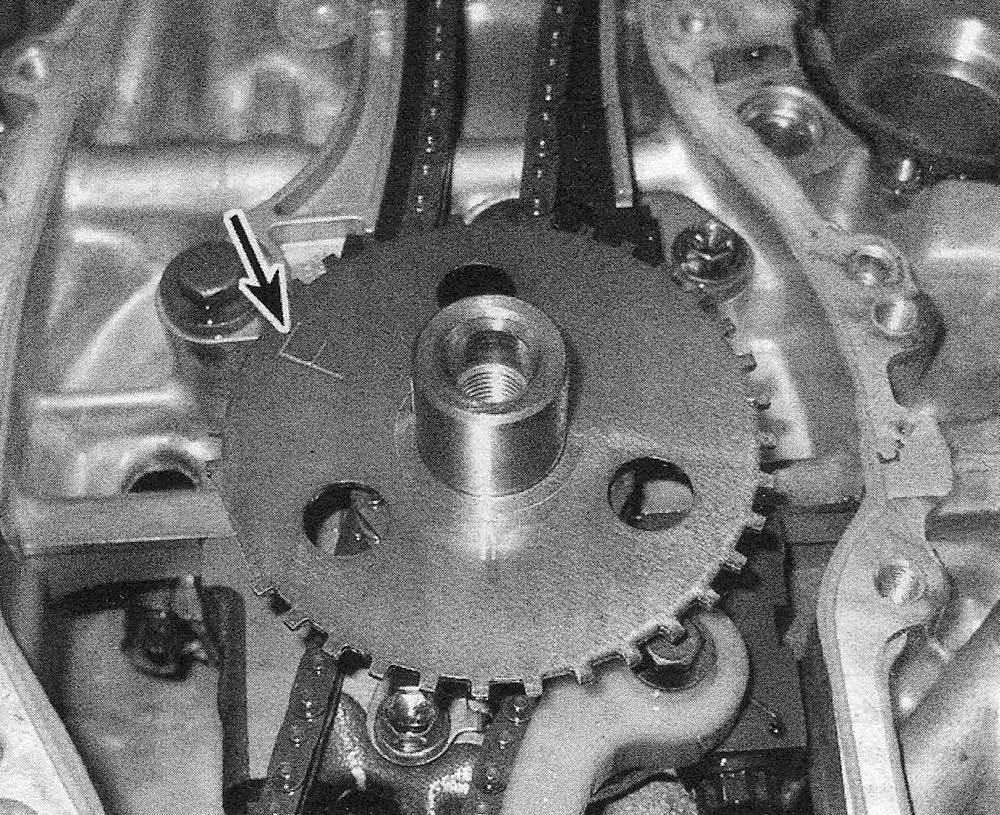
6.7a Verify the engine is at TDC by observing the position of the camshaft sprocket marks (lower arrows) — they must be aligned with the marks on the camshaft bearing caps (upper arrows) (2009 and earlier models
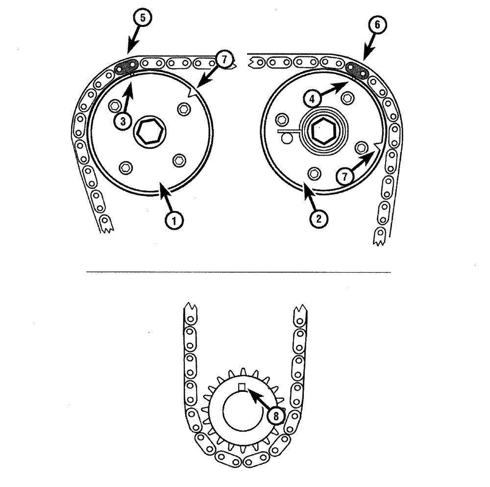
6.7b Camshafts and crankshaft TDC time
1 Intake camshaft sprocket
2 Exhaust camshaft sprockets
3 Intake camshaft sprocket timing mark
4 Exhaust camshaft sprocket timing mark
5 Timing chain «yellow» colored link – intake
8. Remove the crankshaft pulley/vibration damper, being careful not to rotate the engine from TDC (see Crankshaft pulley/vibration damper — removal and installation). If the engine rotates off TDC during this step, reposition the engine back to TDC before proceeding.
10. Remove the passenger side engine mount and movement control rod (see Powertrain mounts — check and replacement).
11. Remove the drivebelt tensioner (s) (see Tune-up and routine maintenance) and the crankshaft position sensor (see Emissions and engine control systems) from the timing chain cover. Also remove the bolt securing the crankshaft position sensor wiring harness to the timing chain cover.
12. Remove the steel oil pan (see Oil pan — removal and installation).
2009 and earlier models
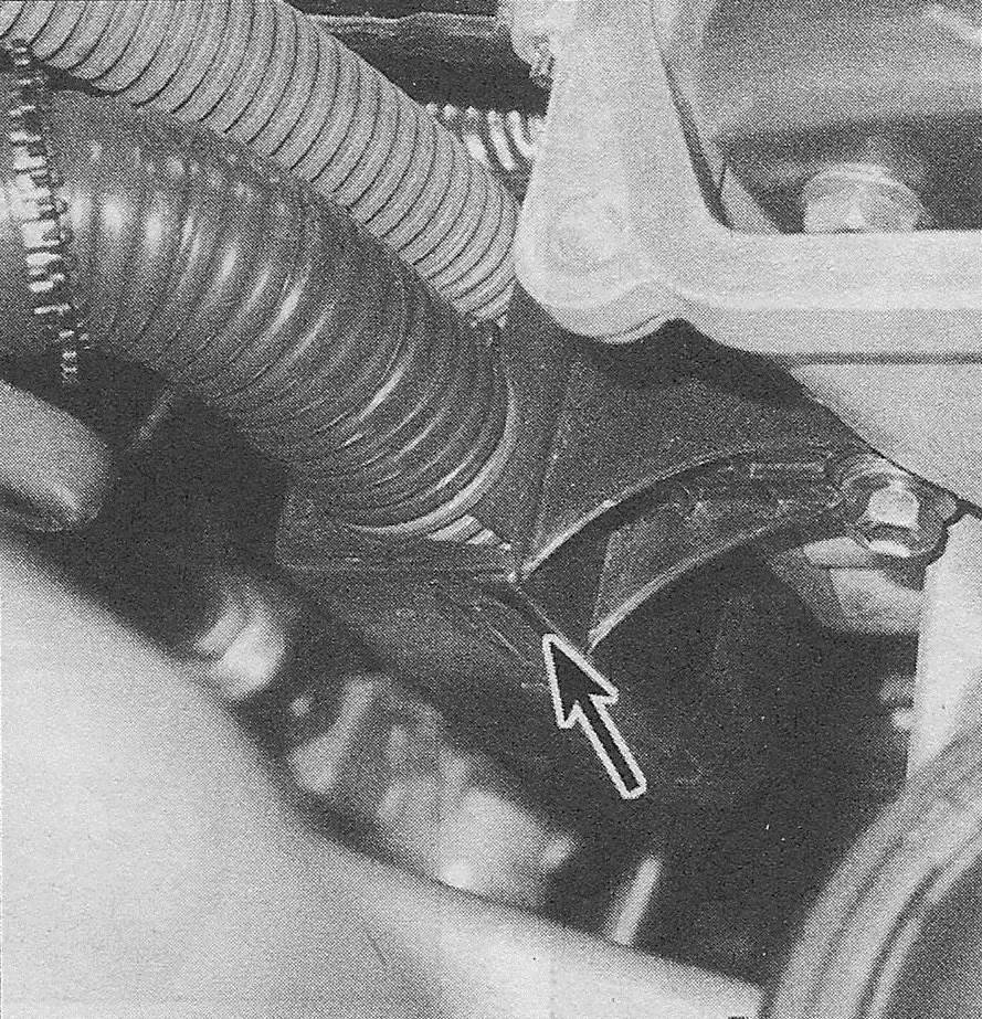
13. Detach the main wiring harness junction and remove the timing chain tensioner from the rear side of the timing chain cover (see illustrations).
6.13a Remove the fasteners securing the main harness to the timing chain cover and position the harness aside — 2009 and earlier models
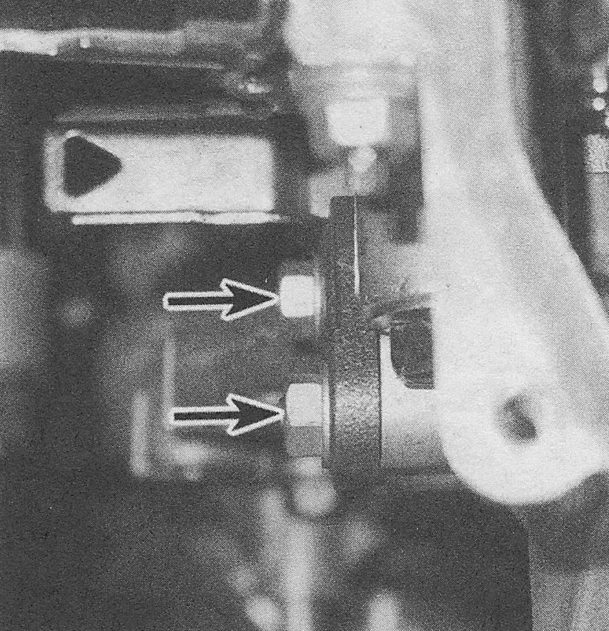
6.13b Timing chain tensioner mounting nuts — 2009 and earlier models
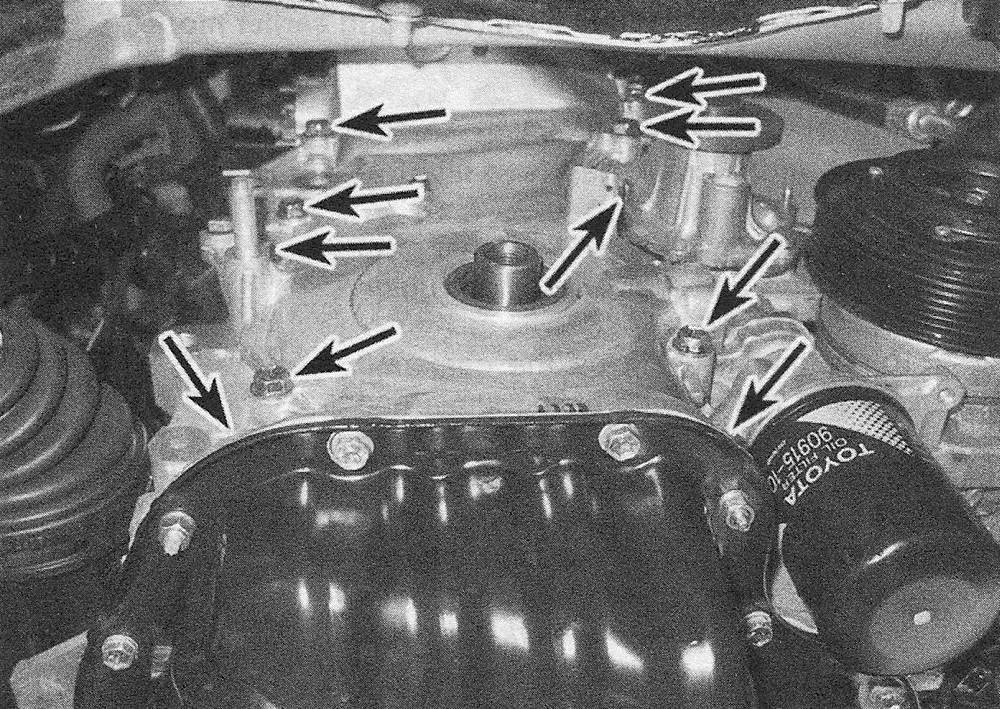
6.14a Timing chain cover upper fasteners
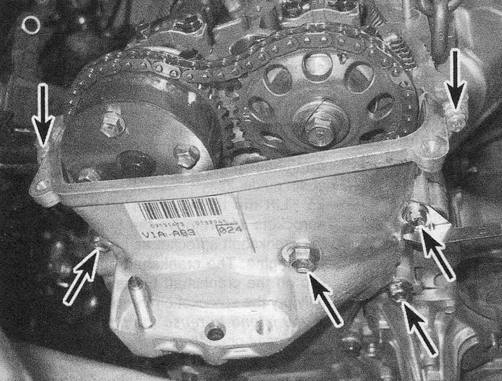
6.14b Timing chain cover lower fasteners; make a note of the fastener sizes, locations and lengths as they are removed, as they must be installed back in their original positions (2009 and earlier models)
6.14c It will be necessary to remove the timing chain cover studs.
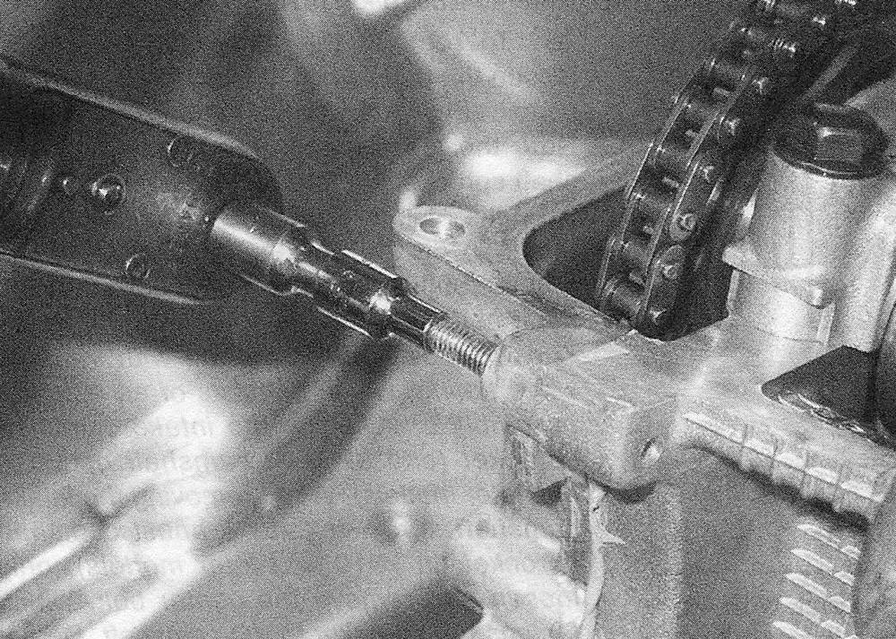
6.14d … before prying the timing chain cover off the engine — 2009 and earlier models
14. Remove the timing chain cover fasteners and pry the cover off the engine (see illustrations).
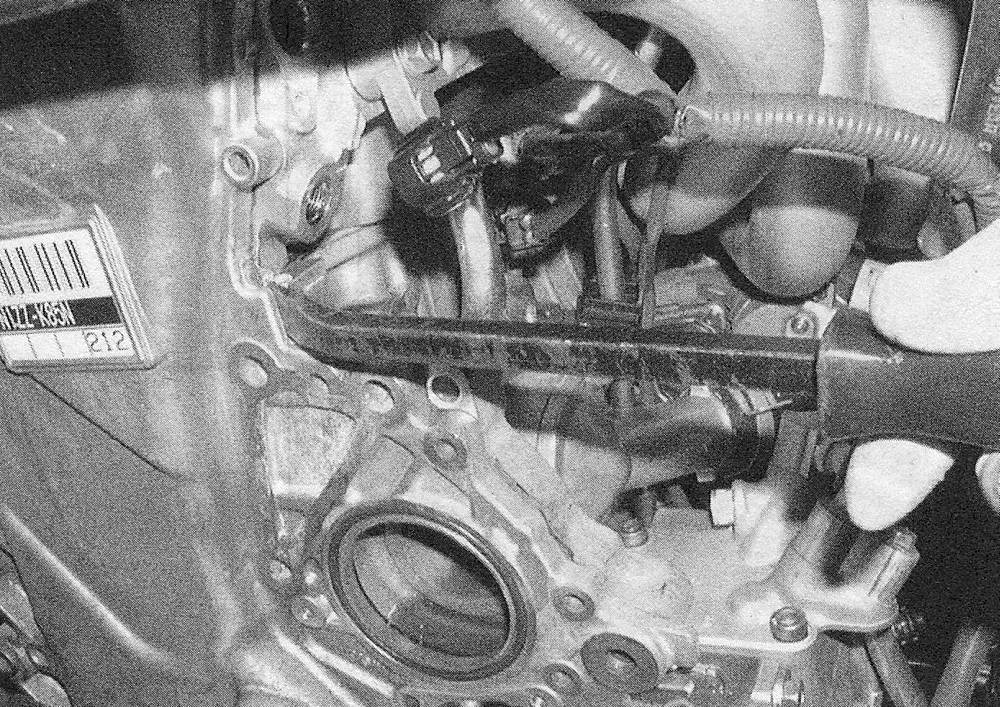
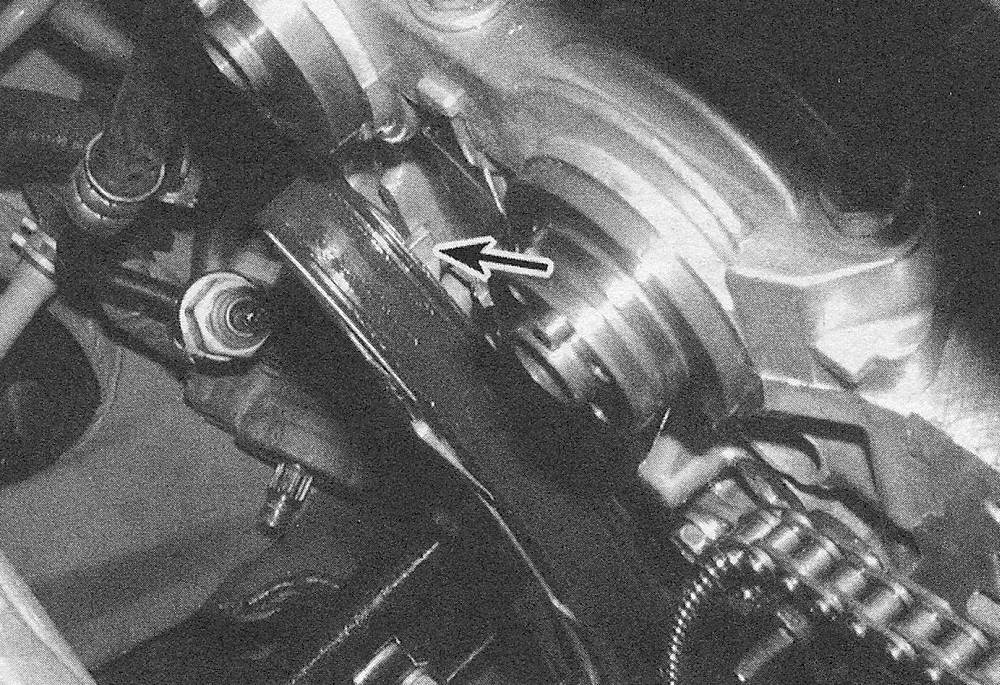
15. Slide the crankshaft position sensor reductor ring off the crankshaft (see illustration).
6.15 Slide the crankshaft position sensor reductor ring off the crankshaft — note the «F» mark on the front (it must be facing outward upon installation) (2009 and earlier models)
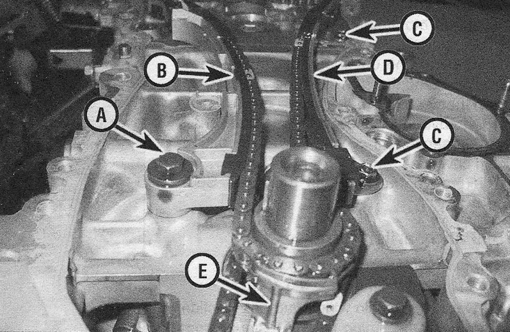
16. Remove the timing chain tensioner pivot arm/chain guide and the lower chain guide (see illustration).
6.16 Timing chain guide mounting details — 2009 and earlier models
- ) A Pivot bolts
- ) Tensioner pivot arm/chain guide
- ) Stationary chain guide mounting bolts
- ) Stationary chain guide
- ) Lower timing chain guide
17. Lift the timing chain off the camshaft sprockets and remove the timing chain and the crankshaft sprocket as an assembly from the engine. The crankshaft sprocket should slip off the crankshaft by hand. If not, carefully pry the sprocket off the crankshaft. Note: If you intend to reuse the timing chain, use white paint or chalk to make a mark indicating the front of the chain. If a used timing chain is reinstalled with the wear pattern in the opposite direction, noise and increased wear may occur.
18. Remove the stationary timing chain guide (see illustration 6.16)
2010 and later models
19. Remove the movement control rod mounting bracket from the front of the timing chain cover (see illustration 6.58), then remove the timing chain cover fasteners and carefully pry the cover off the engine from several locations.
Note: The timing chain cover has several different size mounting bolts; take note of each bolt’s location so they can be returned to the same locations on reassembly.
20. Once the cover is off, remove the 0-rings from the crankcase.
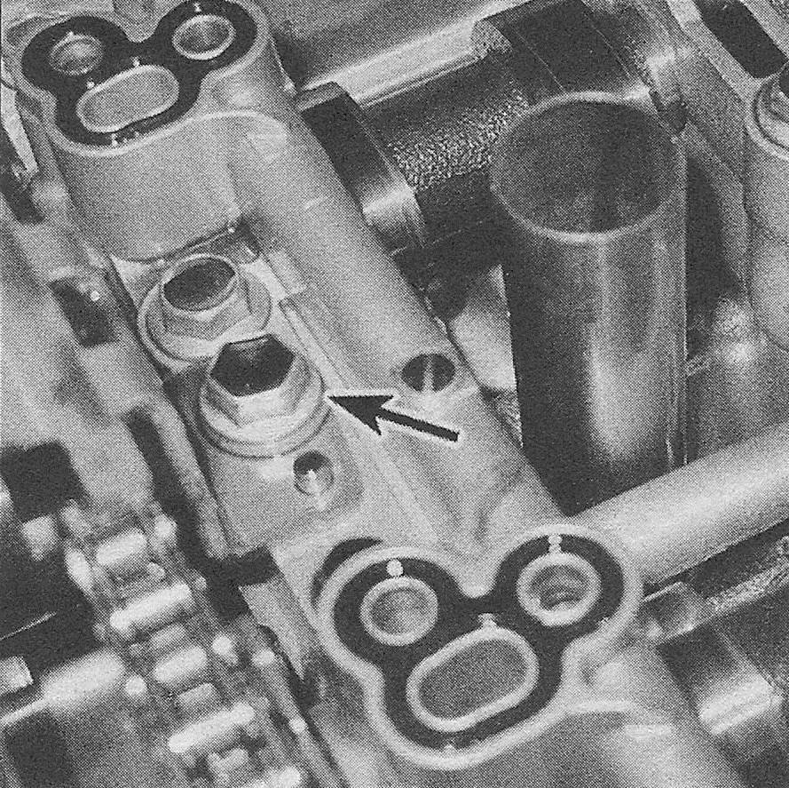
21. Remove the top chain guide mounting bolt and guide (see illustration).
6.21 Top chain guide, mounting bolt and locating pin
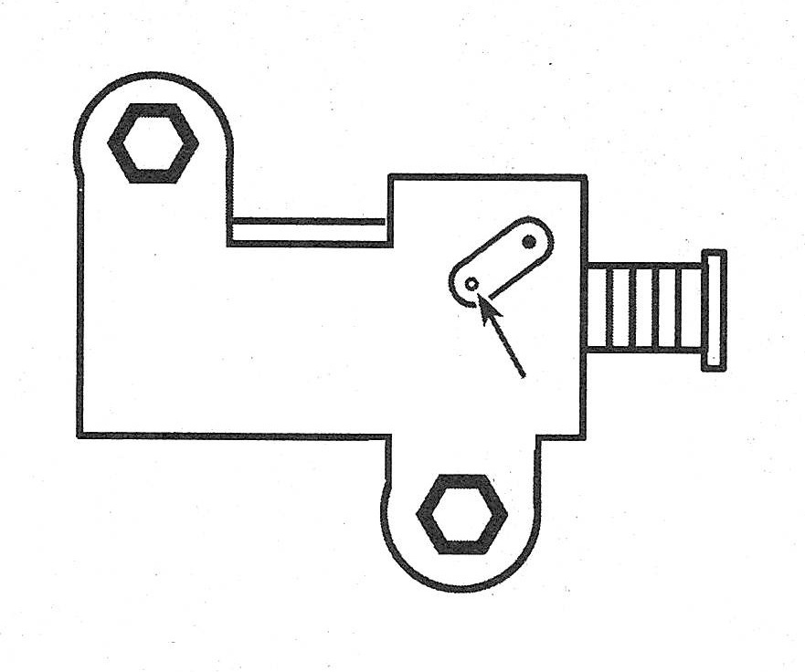
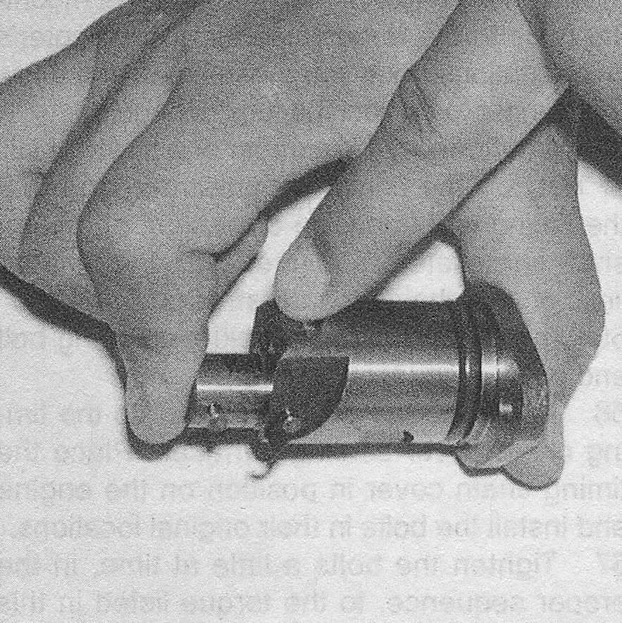
22. Let the tensioner plunger extend until a 0.06-inch (1.5 mm) pin can be inserted into
the alignment holes (see illustration) of the stopper plate and the tensioner. Release the tensioner and make sure the pin is secured.
6.22 Align the hole on the lock with the hole in the tensioner, then insert a 0.06-inch (1.5 mm) pin or drill bit through both components to lock the tensioner
23. Remove the mounting bolts and the timing chain tensioner.
24. Remove the timing chain tensioner pivot arm/chain guide and the stationary timing chain guide.
25. Lift the timing chain off the camshaft sprockets and remove the timing chain and the crankshaft sprocket as an assembly from the engine. The crankshaft sprocket should slip off the crankshaft by hand. If not, carefully pry the sprocket off the crankshaft. Note: If you intend to reuse the timing chain, use white paint or chalk to make a mark indicating the front of the chain. If a used timing chain is reinstalled with the wear pattern in the opposite direction, noise and increased wear may occur.
All models
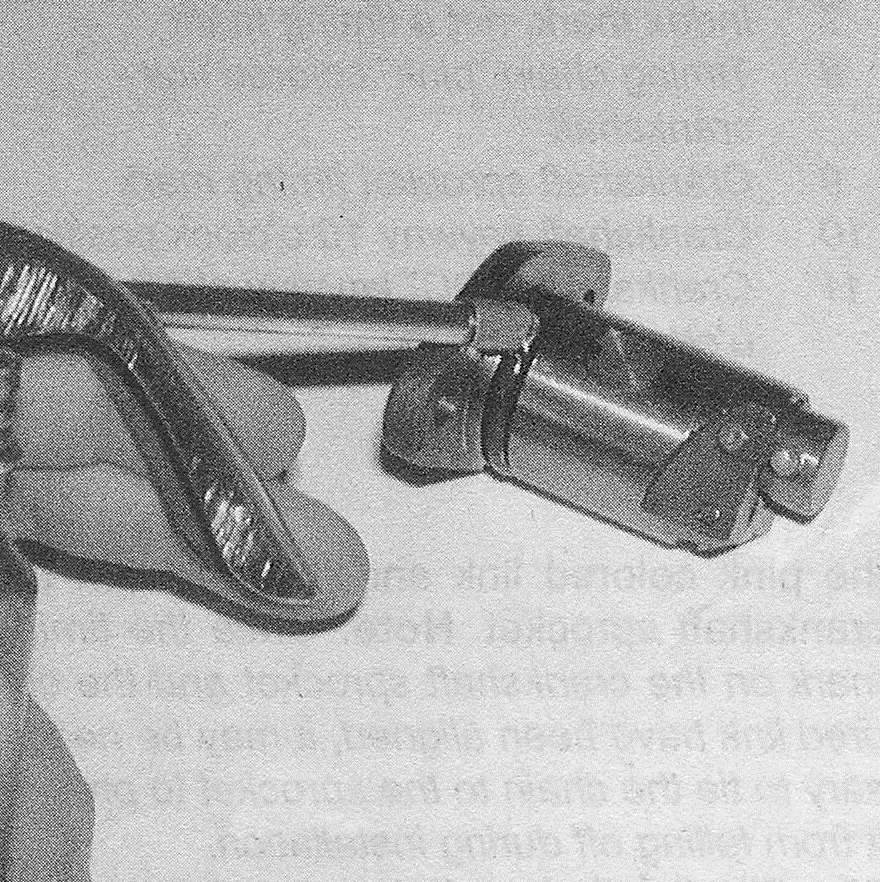
26. To remove the camshaft sprockets, loosen the bolts while holding the hex on the camshaft with a wrench (see illustration). Note the identification marks on the camshaft sprockets before removal, then remove the bolts. Pull on the sprockets by hand until they slip off the dowels. If necessary, use a small puller, with the legs inserted in the relief holes, to pull the sprockets off.
Note: These models are equipped with variable valve timing, which consists of an actuator assembly attached to the intake camshaft sprocket (and exhaust camshaft on 2010 and later models). When removing the intake camshaft sprocket (and exhaust camshaft sprocket on 2010 and later models), only loosen and remove the center bolt, which fastens the sprocket to the camshaft. Do not loosen the outer four bolts that secure the actuator to the sprocket.
6.26 Hold the hex-shaped lug on the camshaft with a wrench to keep it from rotating as the sprocket bolts are loosened — when loosening the camshaft sprocket, loosen only the center bolt which secures the sprocket to the camshaft (2010 and later shown, earlier models similar)
Inspection
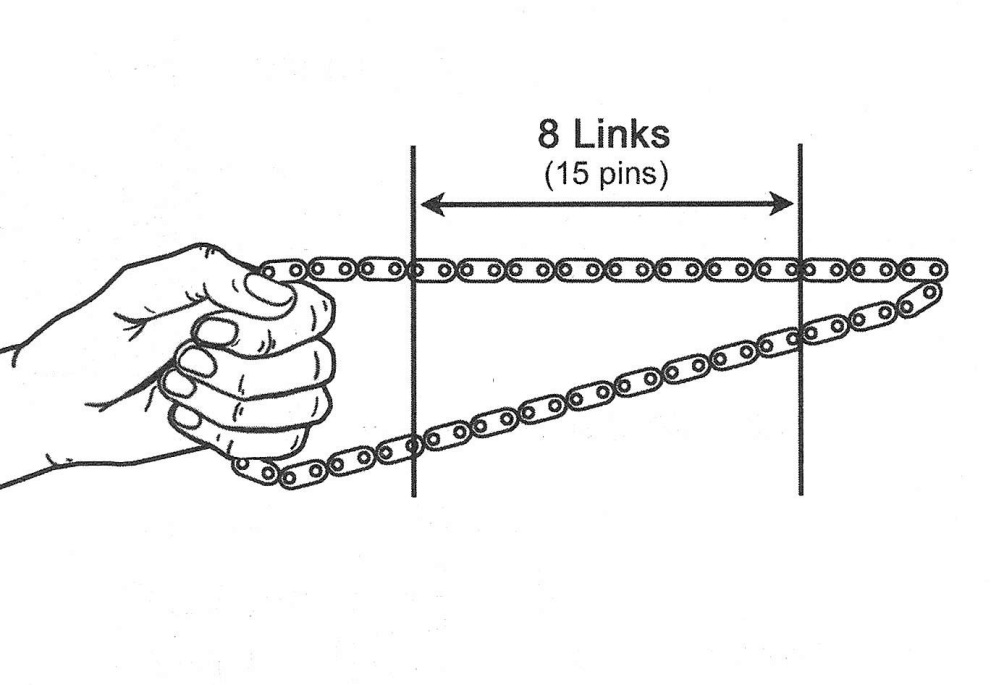
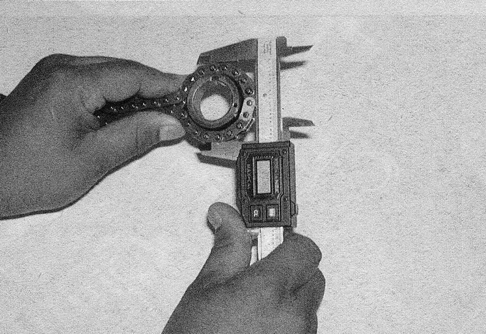
27. Visually inspect all parts for wear and damage. Check the timing chain for loose pins, cracks, worn rollers and side plates. Check the sprockets for hook-shaped, chipped and broken teeth. Also check the timing chain for stretching and the diameter of the timing sprockets for wear with the chain assembled on the sprockets (see illustrations). Be sure to measure across the chain rollers when checking the sprocket diameter and to measure chain stretch at three or more places around the chain. Maximum chain elongation and minimum sprocket diameter (with chain) should not exceed the amount listed in this Chapter’s Specifications. Replace the timing chain and sprockets as a set if the engine has high mileage or fails inspection.
6.27a Timing chain stretch is measured by checking the length of the chain between 8 links (15 pins) at 3 or more places (selected randomly) around the chain — if chain stretch exceeds the specifications between any 8 links, the chain must be replaced
6.27b Wrap the chain around each of the timing sprockets and measure the diameter of the sprockets across the chain rollers —
if the measurement is less than the minimum sprocket diameter, the chain and the timing sprockets must be replaced
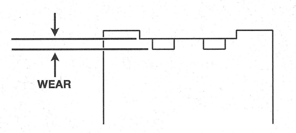
28. Check the chain guides for excessive wear (see illustration). Replace the chain guides if scoring or wear exceeds the amount listed in this Chapter’s Specifications. Note that some scoring of the timing chain guide shoes is normal. If excessive wear is indicated, it will also be necessary to inspect the chain guide oil hole on the front of the block for clogging (see illustration 14.5d).
6.28 Timing chain guide wear is measured from the top of the chain contact surface to the bottom of the wear grooves
Installation
Caution: Before starting the engine, carefully rotate the crankshaft by hand through at least two full revolutions (use a socket and breaker bar on the crankshaft pulley center bolt). If you feel any resistance, STOP! There is something wrong — most likely, valves are contacting the pistons. You must find the problem before proceeding.
29. Remove all traces of old sealant from the timing chain cover and the mating surfaces of the engine block and cylinder head.
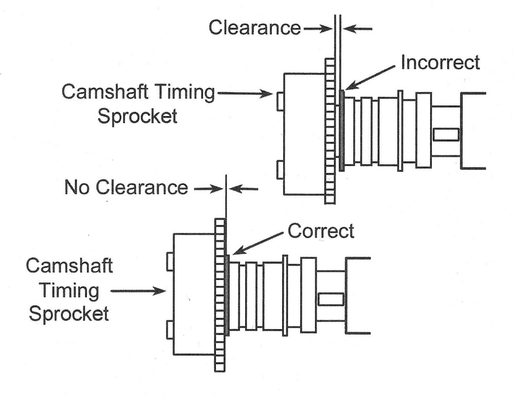
30. Make sure the camshafts are positioned with the dowel pins at the top in the 12 o’clock position, then install both camshaft sprockets in their original locations by aligning the dowel pin hole on the rear of the sprockets with the dowel pin on the camshaft. Apply medium-strength thread locking compound to the camshaft sprocket bolt threads and make sure the washers are in place. Hold the camshaft from turning as described in Step 26 and tighten the bolts to the torque listed in this Chapter’s Specifications. Make sure the camshaft sprocket is fully seated against the camshaft flange (see illustration).
6.30 Camshaft timing sprocket installation details
2009 and earlier models
31. Make sure the TDC marks on the camshaft sprockets are still in alignment (see illustration 6.7a).
32. If the crankshaft has been rotated off TDC during this procedure, it will be necessary to rotate the crankshaft until the keyway is pointing straight up in the 12 o’clock position with the centerline of the cylinder bores.
33. Install the stationary timing chain guide (see illustration 6.16).
34. Loop the timing chain around the crank-
shaft sprocket and align the No.1 colored link with the mark on the crankshaft sprocket. Install the chain and crankshaft sprocket as an assembly on the engine, then install the lower timing chain guide (see illustration).
Note: There are three colored links on the timing chain. The No.1 colored link is the link farthest away from the two-colored links that are closest together.
6.34 Loop the timing chain around the crankshaft sprocket and align the No.1 colored link with the mark on the crankshaft sprocket. Install the chain and crankshaft sprocket as an assembly on the engine and install the lower chain guide
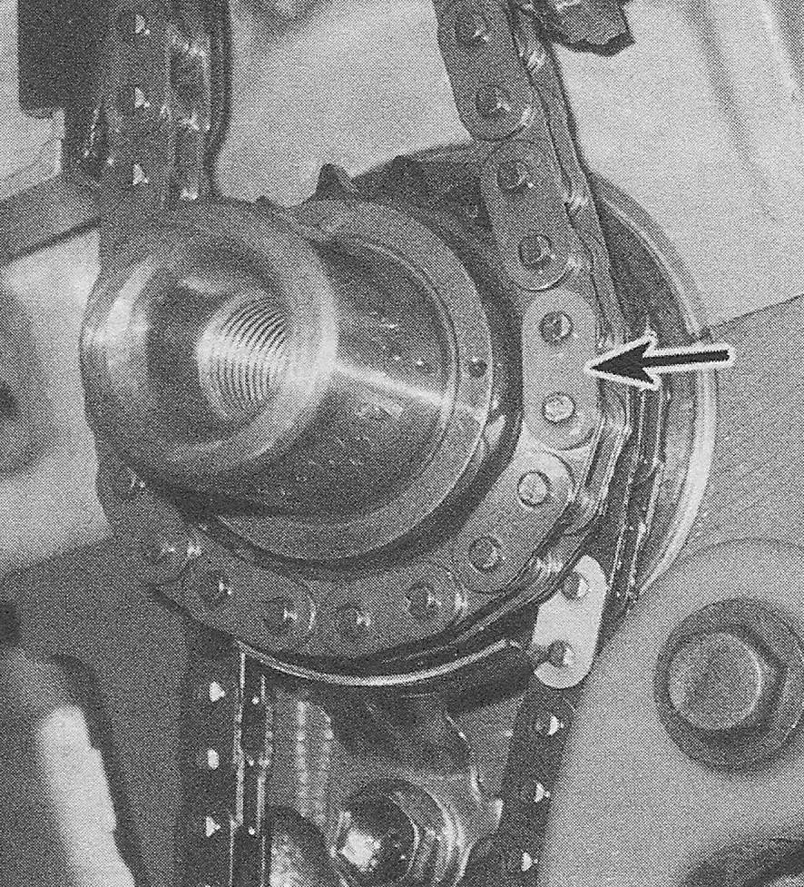
35. Slip the timing chain into the lip of the stationary timing chain guide and over the exhaust camshaft sprocket, then around the intake camshaft sprocket, making sure to align the remaining two-colored links with the marks on the camshaft sprockets (see illustration). Make sure to remove all slack from the right side of the chain when performing this step.
6.35 Loop the timing chain up over the exhaust camshaft and around the intake camshaft, while aligning the remaining two colored links with the marks on the camshaft sprockets
36. Use one hand to remove the slack from the left side of the chain and install the timing chain tensioner pivot arm/chain guide. Tighten the pivot bolt to the torque listed in this Chapter’s Specifications. After installation, make sure the tab on the pivot arm can’t move past the stopper on the cylinder head (see illustration).
6.36 After the tensioner pivot arm is installed, make sure the tab on the pivot arm can’t move past the stopper on the cylinder head
37. Reconfirm that the number one piston is still at TDC on the compression stroke and that the timing marks on the crankshaft and camshaft sprockets are aligned with the colored links on the chain.
38. Install the crankshaft position sensor reductor ring with the «F» mark facing outward (see illustration 6.15).
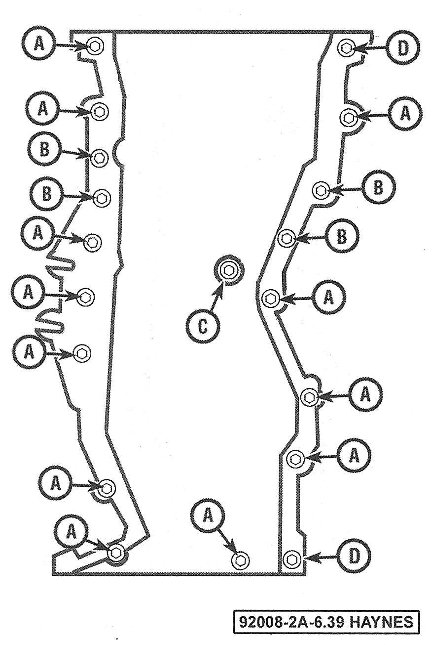
39. Apply a bead of RTV sealant to the timing chain cover sealing surfaces (see illustrations). Place the timing chain cover in position on the engine and install the bolts in their original locations.
6.39a Timing chain cover sealant installation details
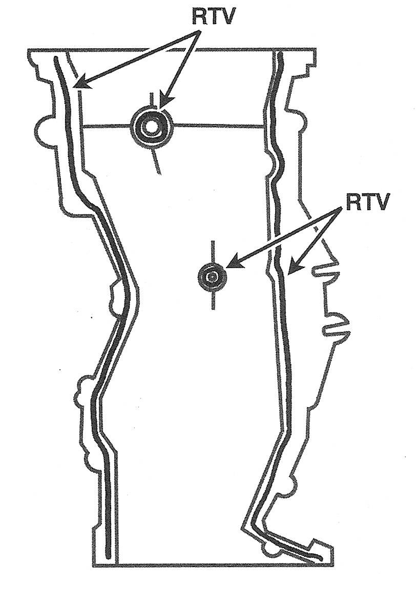
6.39b Also apply a bead of sealant on each side of the parting line between the cylinder head and the engine block
40. Tighten the bolts evenly in several steps to the torque listed in this Chapter’s Specifications. Be sure to follow the sealant manufacturer’s recommendations for assembly and sealant curing times (see illustration).
6.40 Timing chain cover bolt tightening guide — 2009 and earlier models (refer to the Specifications for the torque settings)
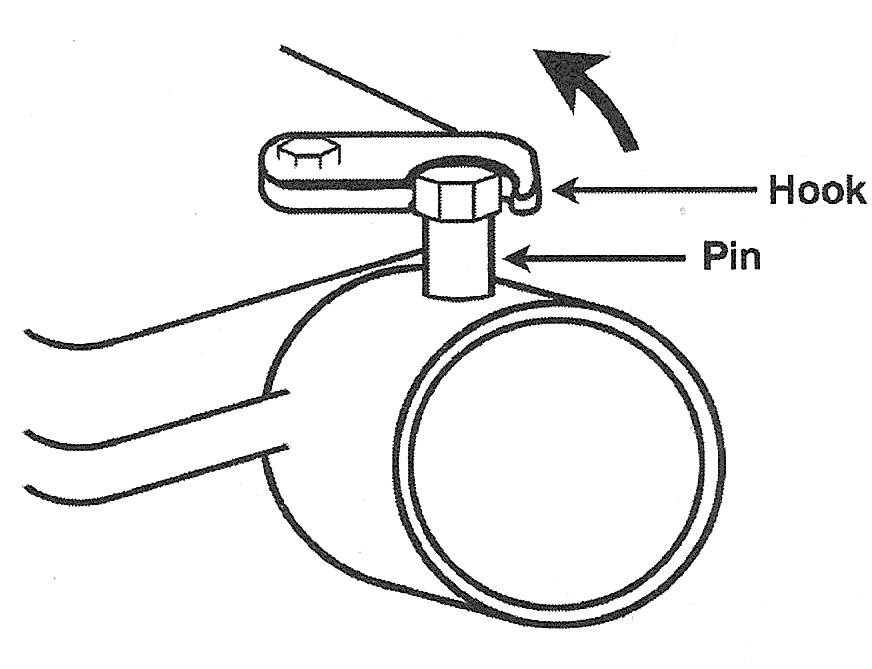
41. Reload and lock the timing chain tensioner to its zero position as follows:
- ) Raise the ratchet pawl and push the plunger inward until it bottoms out (see illustration).
- ) Engage the hook on the tensioner body with the pin on the tensioner plunger to lock the plunger in place.
6.41 Raise the ratchet pawl and push the plunger inward until the hook on the tensioner body can be engaged with the pin on the plunger to lock the plunger in place
42. Lubricate the tensioner 0-ring with a small amount of oil and install the tensioner into the timing chain cover with the hook facing up (see illustration).
6.42 Apply a small amount of oil to the tensioner 0-ring and insert the tensioner into the timing chain cover with the hook facing upward
43. Install the crankshaft pulley/vibration damper (see Crankshaft pulley/vibration damper — removal and installation).
44. Rotate the engine counterclockwise slightly to set the chain tension (see illustration). As the engine is rotated, the hook on the tensioner body should release itself from the pin on the plunger and allow the plunger to spring out and apply tension to the timing chain. If the plunger does not spring outward and apply tension to the timing chain, press downward on the pivot arm and release the hook with a screwdriver. Proceed to Step 60.
6.44 Rotate the engine counterclockwise to disengage the hook from the plunger pin on the tensioner, then rotate it clockwise and confirm that the plunger has extended outward against the pivot arm/chain guide
2010 and later models
45. Temporarily install the crankshaft pulley bolt and rotate the crankshaft counterclockwise until the keyway is pointing to the 10 o’clock position.
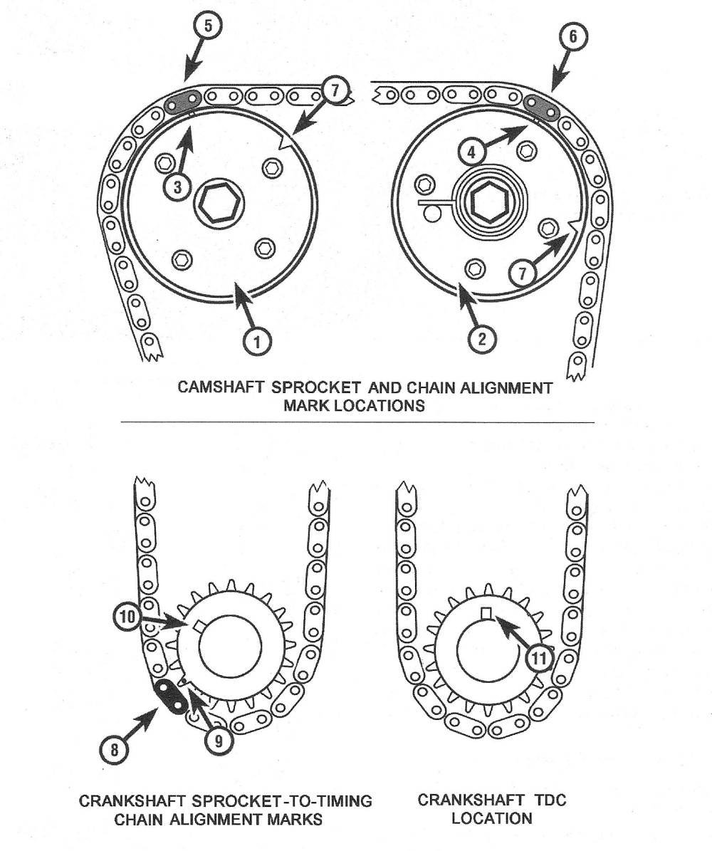
46. Rotate the camshafts as necessary to align the TDC marks on the camshaft sprockets (see illustration).
6.46 2010 and later timing chain alignment details
1. Intake camshaft sprocket
2. Exhaust camshaft sprockets
3. Intake camshaft sprocket timing mark
4. Exhaust camshaft sprocket timing mark
5. Timing chain «yellow» colored link — intake
6. Timing chain «yellow» colored link — exhaust
7. Index mark, not a timing mark
8. Timing chain «pink» colored link -crankshaft
9. Crankshaft sprocket timing mark
10. Crankshaft keyways 10 o’clock position
11. Crankshaft «TDC» keyway at 12 o’clock position
47. Install the stationary timing chain guide.
48. Loop the timing chain around the exhaust camshaft sprocket. Align the yellow-colored link with the exhaust camshaft sprocket timing mark.
Note: There are three colored links on the timing chain. The pink colored link is the link farthest away from the two yellow colored links that are closest together.
49. Guide the chain into the stationary chain guide and align the crankshaft sprocket with the pink colored link and the mark on the crankshaft sprocket. Note: Once the timing mark on the crankshaft sprocket and the colored link have been aligned, it may be necessary to tie the chain to the sprocket to prevent it from falling off during installation.
50. Slip the timing chain around the intake camshaft sprocket but not onto the teeth of the sprocket. Using a wrench on the lug on the intake camshaft, rotate the camshaft counterclockwise to align the timing mark on the intake camshaft sprocket and the chain-colored link. Once the camshaft sprocket and colored link is aligned, install the chain on to the teeth of the camshaft sprocket.
Caution: Do not let go of the wrench holding the intake camshaft sprocket in place until the tensioner is installed.
51. Using your free hand, remove the string holding the chain to the crankshaft sprocket. Rotate just the crankshaft clockwise until the keyway is pointing to the 12 o’clock position and all the slack is removed.
52. Install the tensioner guide and mounting bolt, then tighten the bolt to the torque listed in this Chapter’s Specifications.
53. Install a new gasket and the tensioner with the mounting bolts. Tighten the tensioner mounting bolts to the torque listed in this Chapter’s Specifications, then remove the pin and allow the plunger to contact the tensioner guide.
54. Confirm that the number one piston is still at TDC on the compression stroke and that the timing marks on the crankshaft and camshaft sprockets are aligned with the colored links on the chain (see illustration 6.46).
55. Install the top chain guide mounting bolt and guide.
56. Apply a bead of RTV sealant to the timing chain cover sealing surfaces. Place the timing chain cover in position on the engine and install the bolts in their original locations.
57. Tighten the bolts a little at time, in the proper sequence, to the torque listed in this Chapter’s Specifications (see illustrations). Be sure to follow the sealant manufacturer’s recommendations for assembly and sealant curing times.
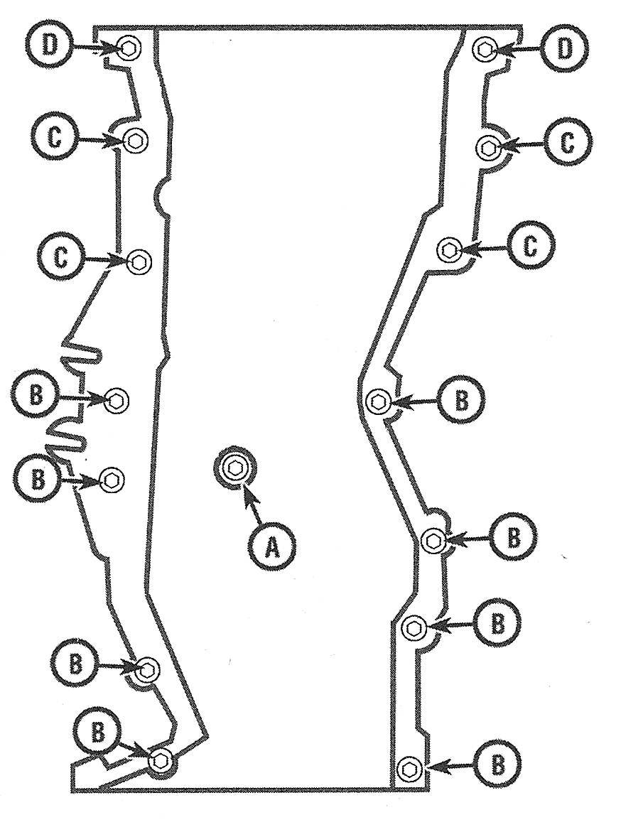
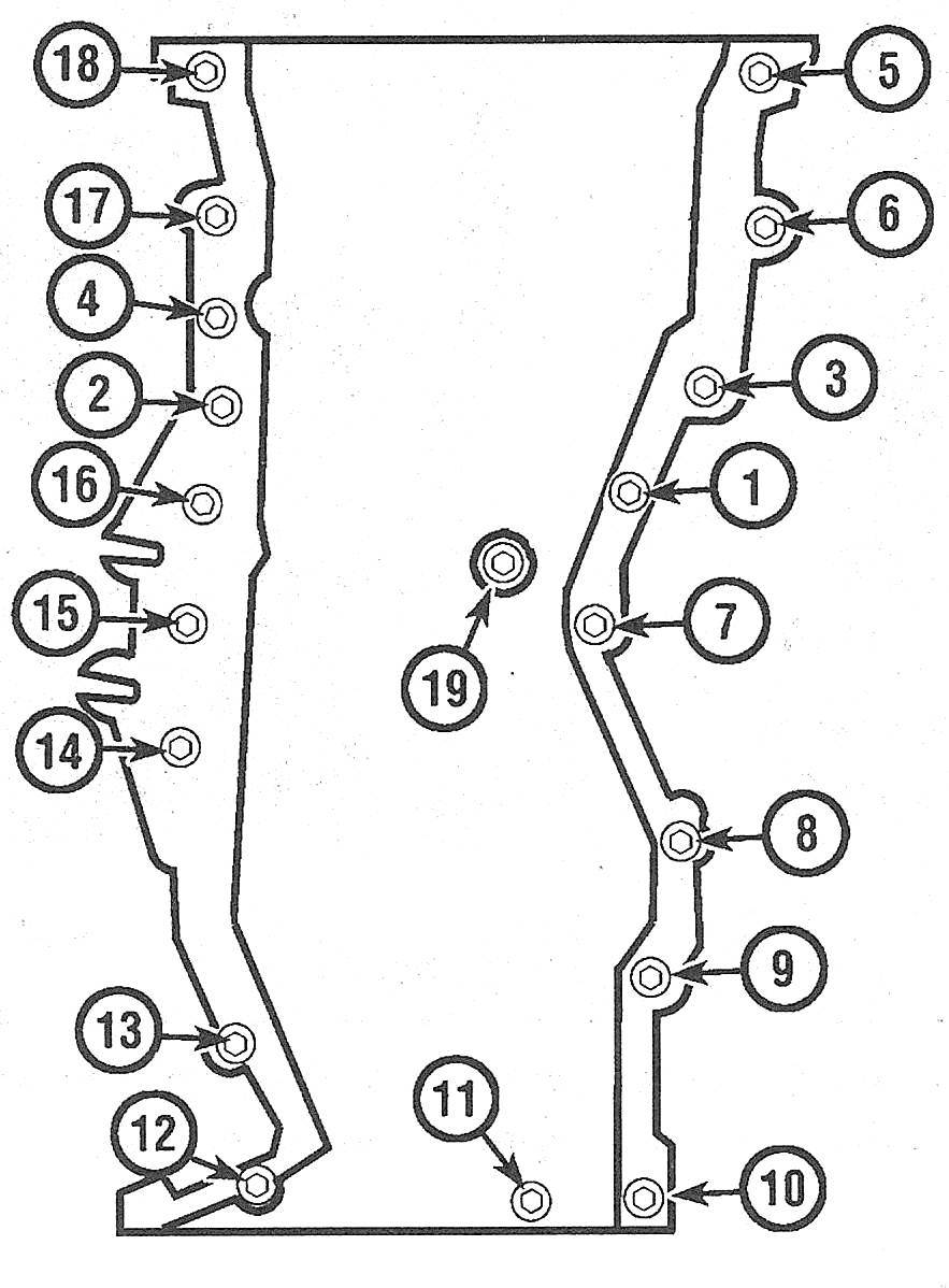
6.57a Timing chain cover bolt identification — 2010 and later models (refer to the Specifications for the torque settings)
6.57b Timing chain cover bolt tightening sequence — 2010 and later models (refer to the Specifications for the torque settings)
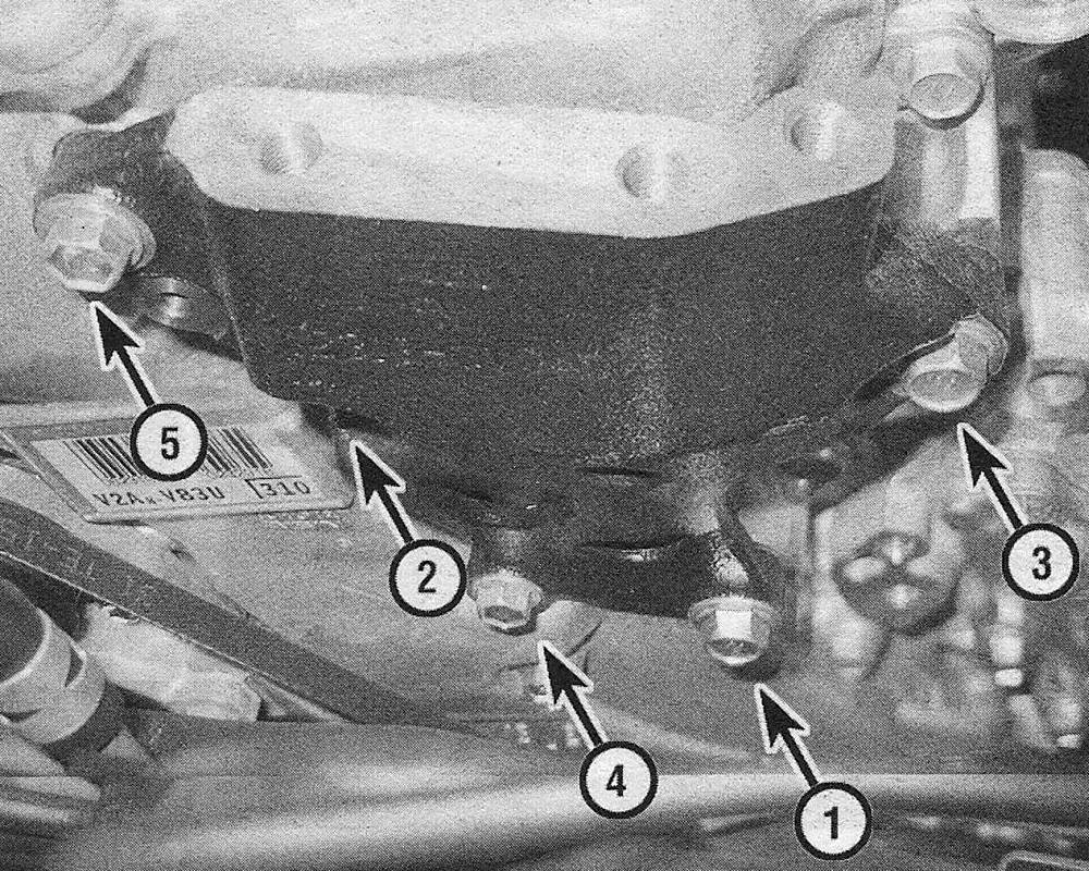
58. Install the movement control rod mounting bracket (see illustration) to the front of the timing chain cover and tighten the bolts in sequence to the torque listed in this Chapter’s Specifications.
6.58 Movement control rod mounting bracket bolt tightening sequence (use the reverse sequence for removal
59. Install the crankshaft pulley/vibration damper (see Crankshaft pulley/vibration damper — removal and installation).
All models
Caution: Carefully rotate the crankshaft by hand through at least two full revolutions (use a socket and breaker bar on the crankshaft pulley center bolt). If you feel any resistance, STOP! There is something wrong — most likely, valves are contacting the pistons. You must find the problem before proceeding.
60. Rotate the engine clockwise at least two revolutions and reposition the number one piston at TDC on the compression stroke (see Top Dead Center (TDC) for number one piston — locating). Visually confirm that the timing mark on the crankshaft pulley/vibration damper is aligned with the «0» mark on the timing chain cover and the camshaft sprocket marks are aligned and parallel with the top of the timing chain cover as shown in illustrations 6.7a or 6.7b.
61. The remainder of installation is the reverse of removal.