Valve clearance check and adjustment (2009 and earlier four-cylinder models)
Warning: These models are equipped with airbags. Always disable the airbag system before working in the vicinity of any airbag system component to avoid the possibility of accidental deployment of the airbag (s), which could cause personal injury (see Chassis electrical system). Note: All V6 engines and 2010 and later four-cylinder engines have hydraulic lash adjusters that don’t require checking or adjustment.
Check
1. Disconnect the negative cable from the battery (see Engine electrical systems).
2. Remove the ignition coils (see Engine electrical systems) and any other components that will interfere with valve cover removal.
3. Blowout the recessed area around the spark plug openings with compressed air, if available, to remove any debris that might fall into the cylinders, then remove the spark plugs (see Spark plug check and replacement).
4. Remove the valve cover (see Four-cylinder engines).
5. Refer to Chapter Four-cylinder engines and position the number 1 piston at TDC on the compression stroke.
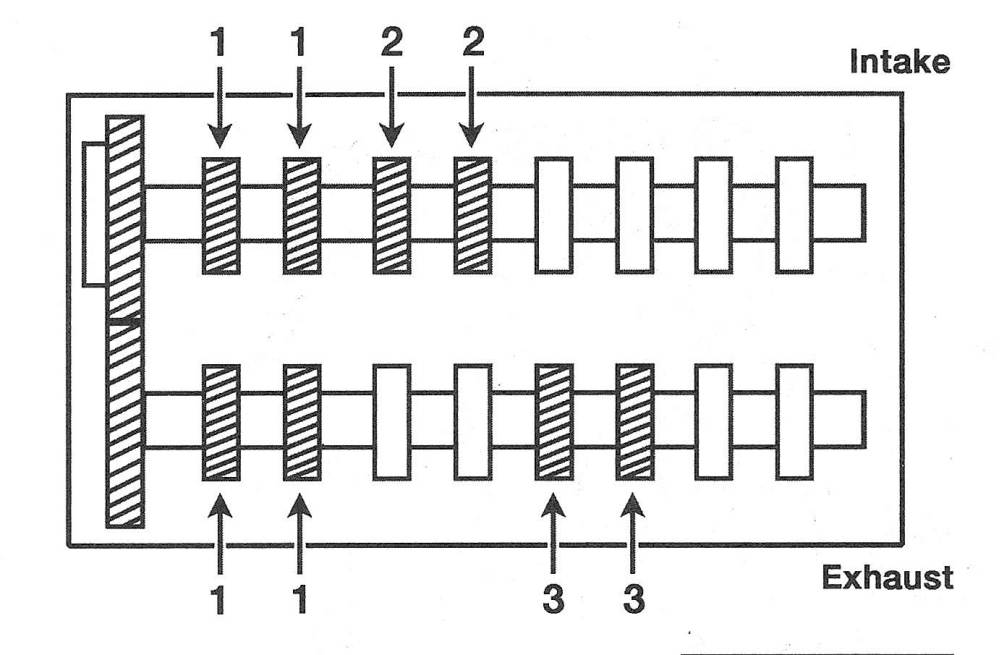
6. Measure the clearances of the indicated
valves with feeler gauges (see illustration). Record the measurements which are out of specification. They will be used later to determine the required replacement lifters.
28.6 When the no. 1 piston is at TDC on the compression stroke, the valve clearance for the no. 1 and no. 3 cylinder exhaust valves and the no. 1 and no. 2 cylinder intake valves can be measured
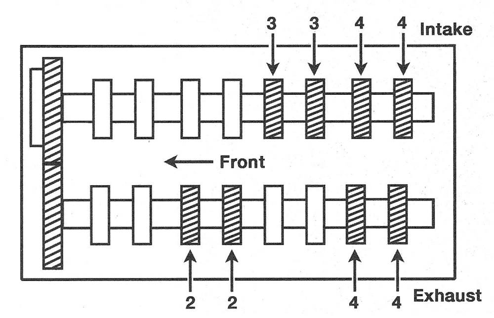
7. Turn the crankshaft one complete revolution and realign the timing marks. Measure the remaining valves (see illustration).
28.7 When the no. 4 piston is at TDC on the compression stroke, the valve clearance for the no. 2 and no. 4 exhaust valves and the no. 3 and no. 4 intake valves can be measured
Adjustment
8. If any of the valve clearances were out of adjustment, remove the camshaft (s) from over the lifter(s) that was/were out of the specified clearance range (see Four-cylinder engines).
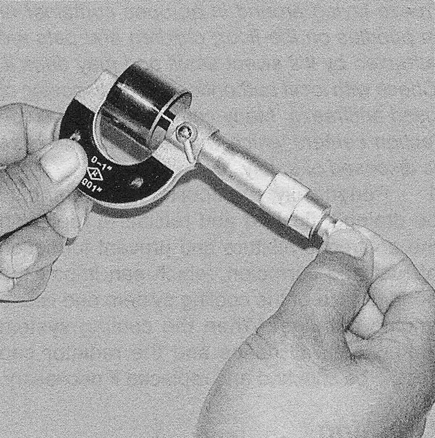
9. Measure the thickness of the lifter with a micrometer (see illustration). To calculate the correct thickness of a replacement lifter that will place the valve clearance within the specified value, use the following formula:
N = T + (A — V)
T = thickness of the old lifter
A = valve clearance measured
N = thickness of the new lifter
V = desired valve clearance (see this Chapter’s Specifications)
28.9 Measure the thickness of the lifter head with a micrometer
10. Select a lifter with a thickness as close as possible to the valve clearance calculated. The lifters are available in 35 sizes in increments of 0.0008-inch (0.020 mm), ranging in size from 0.1992-inch (5.060 mm) to 0.2260-inch (5.740 mm).
11. Install the proper thickness lifter (s) in position, making sure to lubricate them with camshaft installation lube first.
Note: Apply the lubricant to the underside of the lifter where it contacts the valve stem, the walls of the lifter and the face of the lifter.
12. Install the camshaft (s) (see Four-cylinder engines).
13. The remainder of installation is the reverse of removal