Camshafts, rocker arms and valve adjusters — removal, inspection and installation
Removal
Note: The manufacturer recommends removing the engine and transaxle assembly to perform this procedure.
Note: The following procedure is not for beginners. Please read the entire procedure carefully before deciding whether this is a job that you want to tackle at home.
1. Remove the engine and transaxle.
2. Drain the engine oil and coolant (see Tune-up and routine maintenance).
3. Remove the timing chains and sprockets (see Timing chains and sprockets — removal, inspection and installation).
4. Before removing the camshafts from the right (rear bank) cylinder head, check to make sure that the nose of the intake cam lobe for the No. 1 cylinder is facing toward 12 o’clock, and the nose of the exhaust cam lobe is facing approximately 3 o’clock (the locating pins at the front of the camshaft should be at 12 o’clock for the exhaust cam and approximately 1:30 for the intake cam).
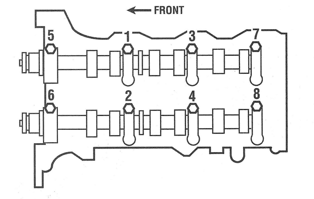
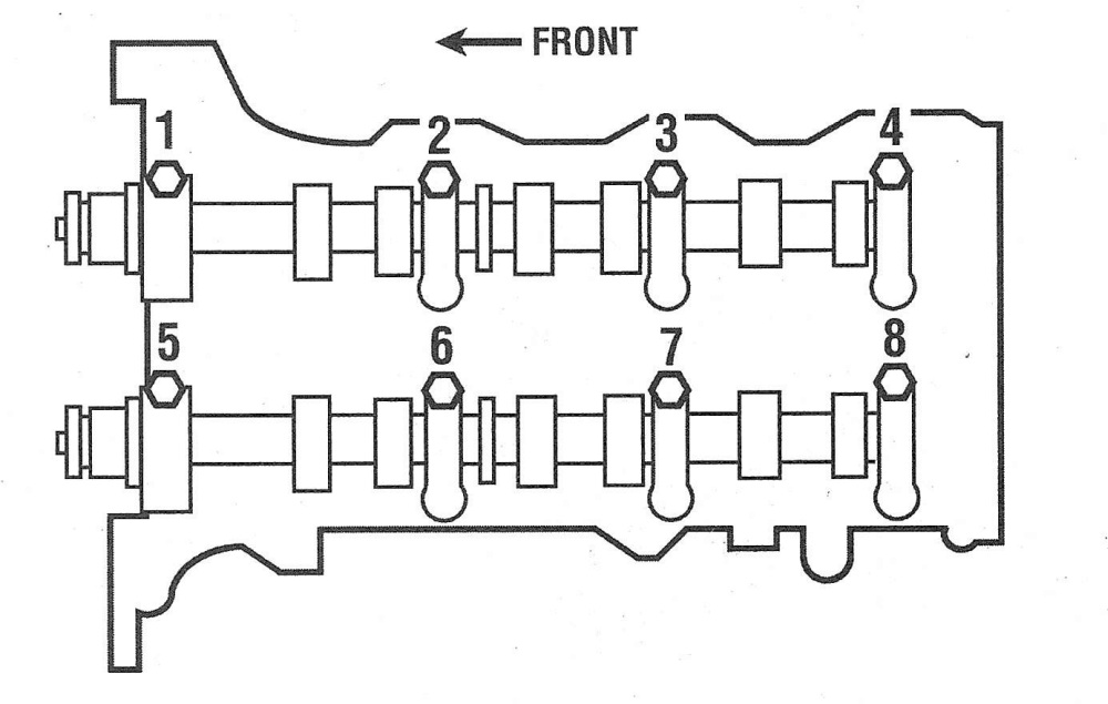
5. Gradually loosen and remove the 8 (smaller) bearing cap bolts in the reverse of the tightening sequence (see illustrations 9.19a and 9.19b).
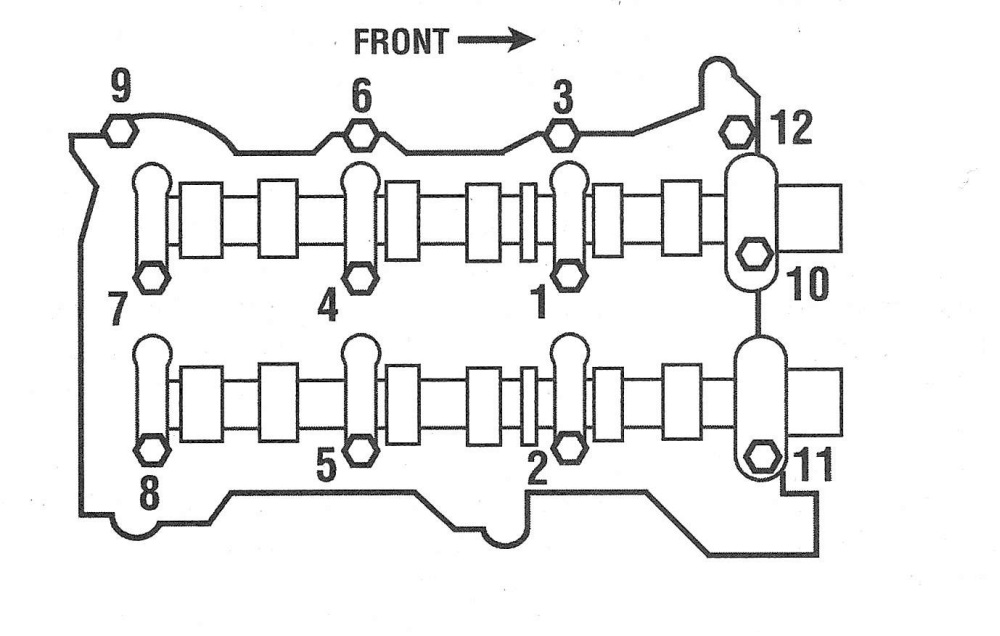
6. Gradually loosen and remove the remaining 12 housing bolts in the reverse of the tightening sequence (see illustrations 9.18a and 9.18b).
7. Remove all five bearing caps and remove the intake and exhaust camshafts. Be sure to keep all of the components in the correct order. One way to do this is to put them in a box and label the cap numbers with a utility marker pen.
8. Carefully pry the camshaft housing from the top of the cylinder head.
Caution: Use a screwdriver wrapped with tape to avoid scratching the parts.
9. Remove all of the rocker arms and lash adjusters and put them in the same box with the cam bearing caps. Every component should be marked or labeled so that it can be returned to its original location.
10. If you’re removing the camshafts from the front bank cylinder head, repeat Steps 5 through 9. Make sure that the front camshaft lobes on the intake cam are positioned at 9 o’clock and the exhaust cam at 1 o’clock (the locating pins at the front of the camshaft should be at 12 o’clock for both cams). Caution: While the timing chains and camshafts are removed, DO NOT ROTATE THE CRANKSHAFT!
Inspection
11. Inspect each rocker and lash adjuster arm for wear.
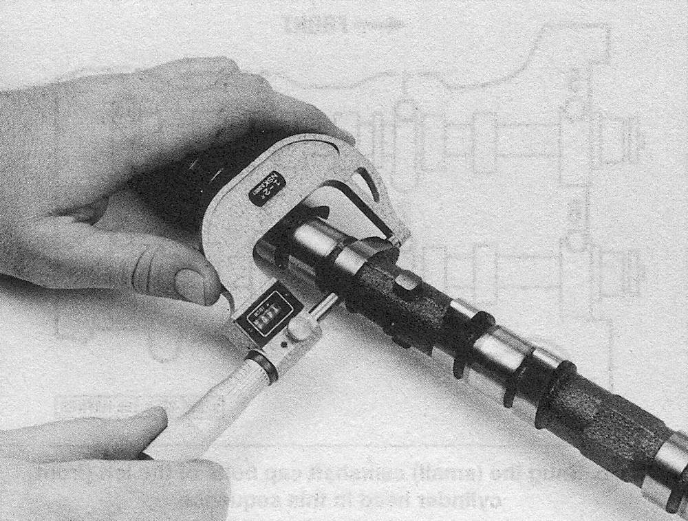
12. Visually examine the cam lobes and bearing journals for score marks, pitting, galling and evidence of overheating (blue, discolored areas). Look for flaking away of the hardened surface layer of each lobe. Using a micrometer, measure the height of each camshaft lobe (see illustration). Compare your measurements with this Chapter’s Specifications. If the height for any one lobe is less than the specified minimum, replace the camshaft.
9.12 Measure the lobe heights on each camshaft — if any lobe height is less than the specified allowable minimum replaces that camshaft
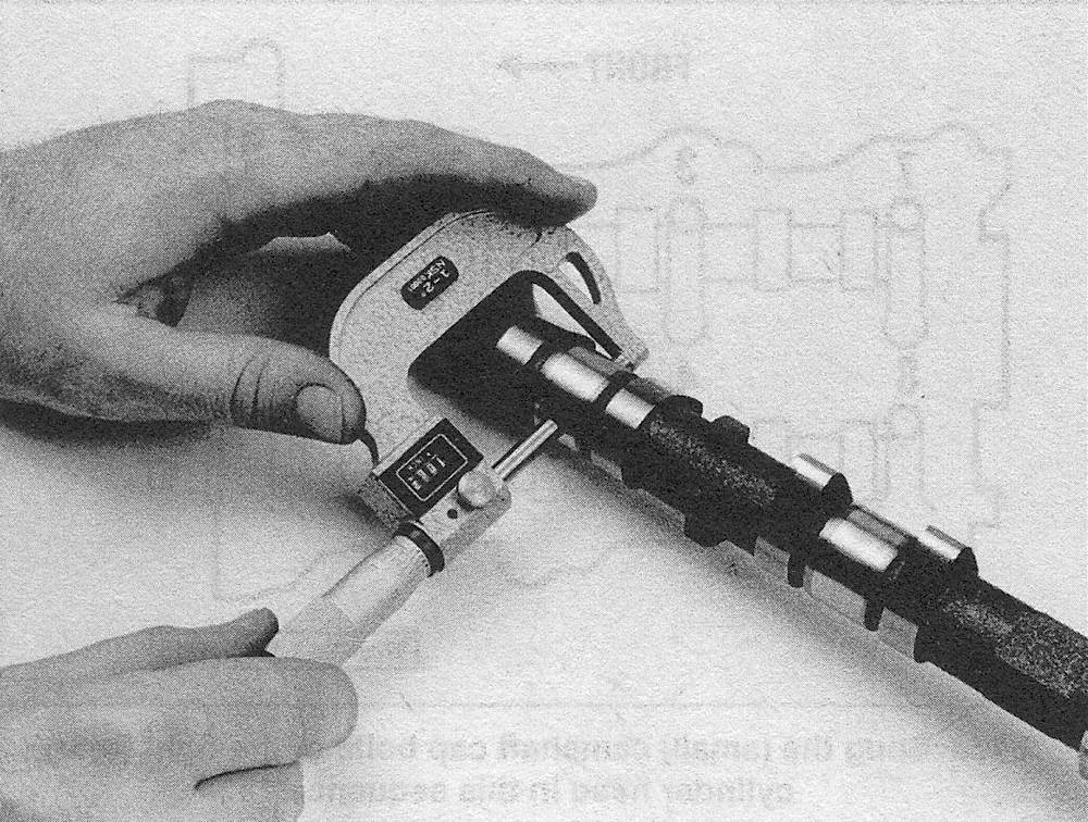
13. Using a micrometer, measure the diameter of each journal at several points (see illustration). Compare your measurements with this Chapter’s Specifications. If the diameter of any one journal is less than specified, replace the camshaft.
9.13 Measure each journal diameter with a micrometer if any journal measures less than the specified limit, replace the camshaft
14. Check the oil clearance for each camshaft journal as follows:
- ) Clean the bearing caps and the camshaft journals with brake system cleaner.
- ) Carefully lay the camshaft (s) in place in the cylinder head. Don’t install the lifters and don’t use any lubrication.
- ) Lay a strip of Pasturage on each journal.
- ) Install the bearing caps with the arrows pointing toward the front (timing chain end) of the engine.
- ) Tighten the bolts to the torque listed in this Chapter’s Specifications in 1/4-turn increments.
Note: Don’t turn the camshaft while the Pasturage is in place. - ) Remove the bolts and detach the caps.
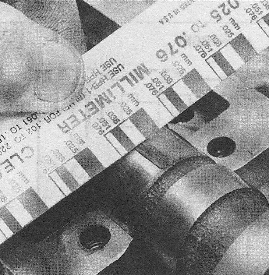
- ) Compare the width of the crushed Pasturage (at its widest point) to the scale on the Pasturage envelope (see illustration).
- ) If the clearance is greater than specified, replace the camshaft and/or cylinder
- ) Scrape off the Pasturage with your fingernail or the edge of a credit card -don’t scratch or nick the journals or bearing caps.
9.14 Compare the width of the crushed Plastigage to the scale on the envelope to determine the oil clearance
Installation
15. Lightly lubricate the lash adjuster bores and the adjusters themselves with clean engine oil, then install them in the same bores from which they were removed. Install the rocker arms in their original positions, oiling all wear points as you do so.
16. Right side (rear cylinder bank): Lubricate the camshaft journals and lobes with camshaft installation lubricant. Install the camshafts on the right camshaft housing so that the locating pin of the exhaust camshaft is at 12 o’clock and the intake camshaft’s locating pin is rotated approximately 45 degrees to 1:30. Apply a light coat of engine oil to the upper bearing caps, then install them in their correct locations. Tighten the bolts snug at this time in the correct sequence (see illustrations).
9.16a Snug the (small) camshaft cap bolts of the right (rear) cylinder head in this sequence
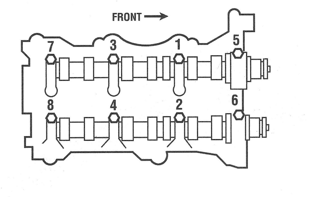
9.16b Snug the (small) camshaft cap bolts of the left (front) cylinder head in this sequence
17. Thoroughly clean the sealing surfaces of the bottom of the camshaft bearing sup- port and the top of the cylinder head. Apply a continuous 1/8-inch to 3/16-inch bead of RTV silicone sealer to the surface of the top of the cylinder head that mates with the camshaft bearing housing.
18. Set the camshaft housing assembly into place. Install the 12 mounting bolts and
tighten them in the correct sequence to the torque listed in this Chapter’s Specifications (see illustrations).
9.18a Camshaft housing bolt tightening sequence right (rear) cylinder head
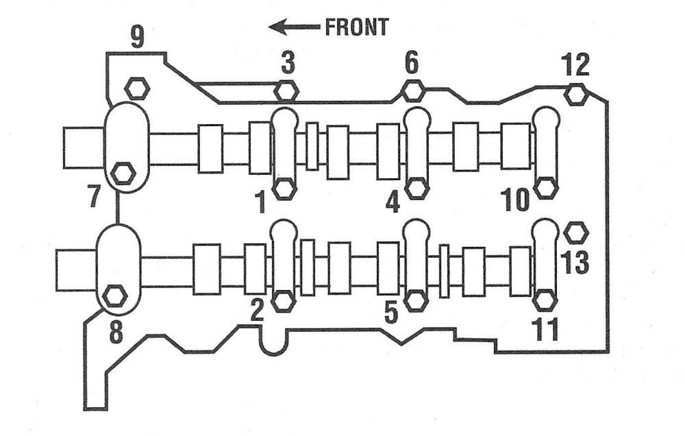
9.18b Ca shaft housing bolt tightening sequence — left (front) cylinder head
19. Install the remaining (smaller) bearing cap bolts, then tighten them in the correct sequence to the torque listed in this Chapter’s Specifications (see illustrations).
9.19a Camshaft bearing cap bolt tightening sequence — small bolts — for the right (rear) cylinder head
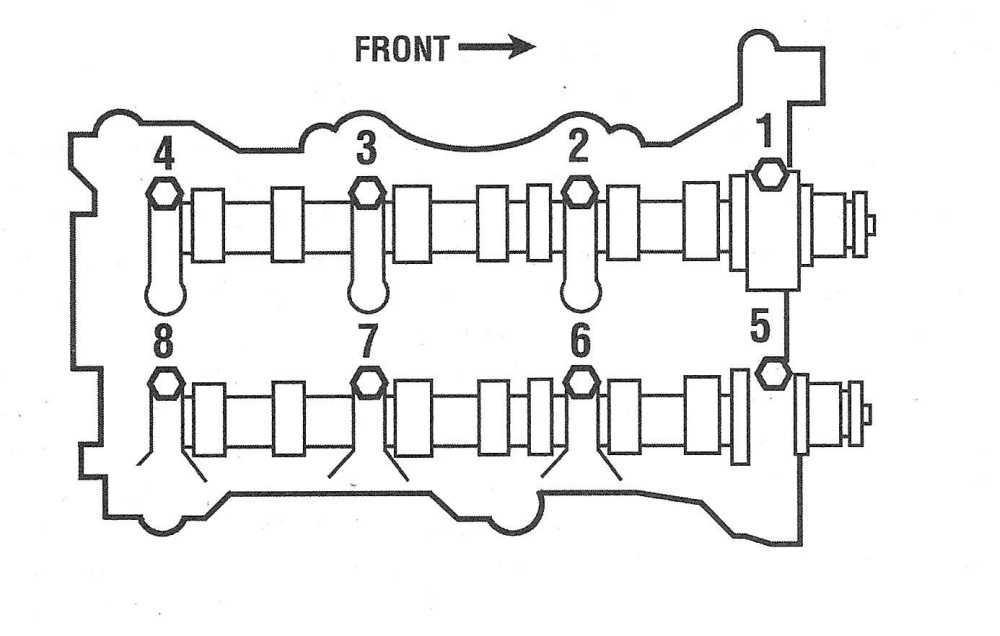
9.19b Camshaft cap bolt tightening sequence small bolts — for the left (front) cylinder head
20. Left side (front cylinder bank): Lightly lubricate the camshaft journals with camshaft installation lubricant. Install the camshafts on the left cylinder head so that the locating pin of each camshaft is in the 12 o’clock position. Proceed as with the right cylinder head. Note: There are 13 bolts in the camshaft housing instead of 12.
21. The remainder of installation is the reverse of removal. Install the timing chains, the timing chain cover and all of the components attached to the cover (see Timing chains and sprockets — removal, inspection and installation).
Caution: Carefully rotate the crankshaft by hand through at least two full revolutions (use a socket and breaker bar on the crankshaft pulley center bolt). If you feel any resistance, STOP! There is something wrong — most likely valves are contacting the pistons. You must find the problem before proceeding.
22. Refill the engine with oil and coolant (see Tune-up and routine maintenance), reconnect the cable to the negative battery terminal, start the engine and check for leaks. Note: It may take a few minutes for lifter clatter to disappear.