Timing chains and sprockets — removal, inspection and installation
Removal
Warning: Wait until the engine is completely cool before beginning this procedure.
Caution: The timing system is complex, and severe engine damage will occur if you make any mistakes. Do not attempt this procedure unless you are highly experienced with this type of repair. If you are at all unsure of your abilities, be sure to consult an expert. Double-check all your work and be sure everything is correct before you attempt to start the engine.
Note: The manufacturer recommends removing the engine and transaxle assembly to perform this procedure.
1. Remove the engine/transaxle assembly.
2. Remove the drivebelt, unbolt the drive- belt tensioner (see Drivebelt check and replacement in Chapter Tune-up and routine maintenance), remove the idler pulley bolts and remove the two idler pulleys.
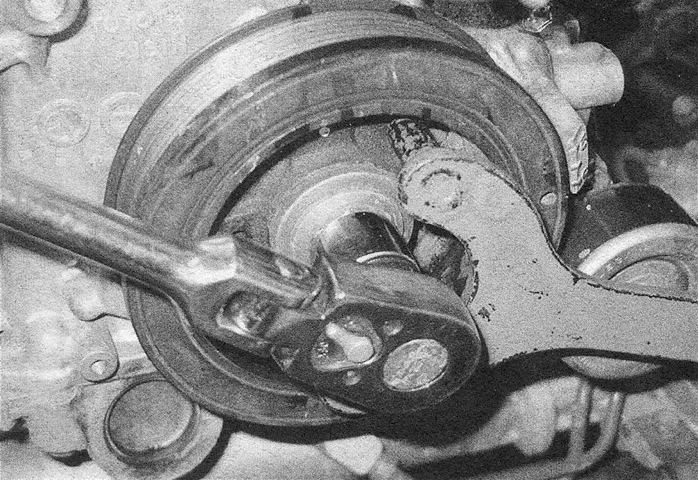
3. Set the engine to TDC (see Top Dead Center (TDC) for number one piston — locating). Remove the crankshaft pulley (see illustrations).
7.3a Hold the crankshaft pulley with a pin spanner while removing the bolt
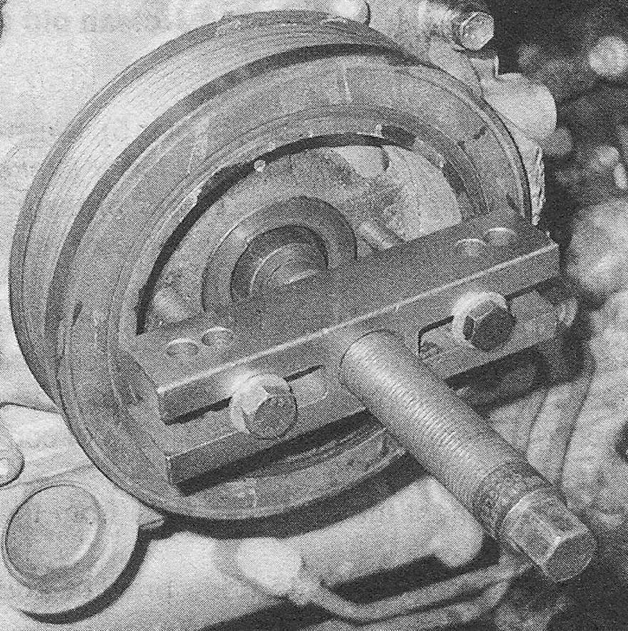
7.3b If the crankshaft pulley can’t be removed by hand, use a puller that bolts to the hub of the pulley, not a jaw- type puller. Also, be sure to use the correct adapter between the nose of the crankshaft and the puller screw, so as not to damage the threads in the crankshaft
4. Remove the four timing chain cover bolts from the front of the upper oil pan.
5. Remove the water inlet (see Cooling, heating and air conditioning systems). Remove the 0-ring and gasket from the water inlet and discard them.
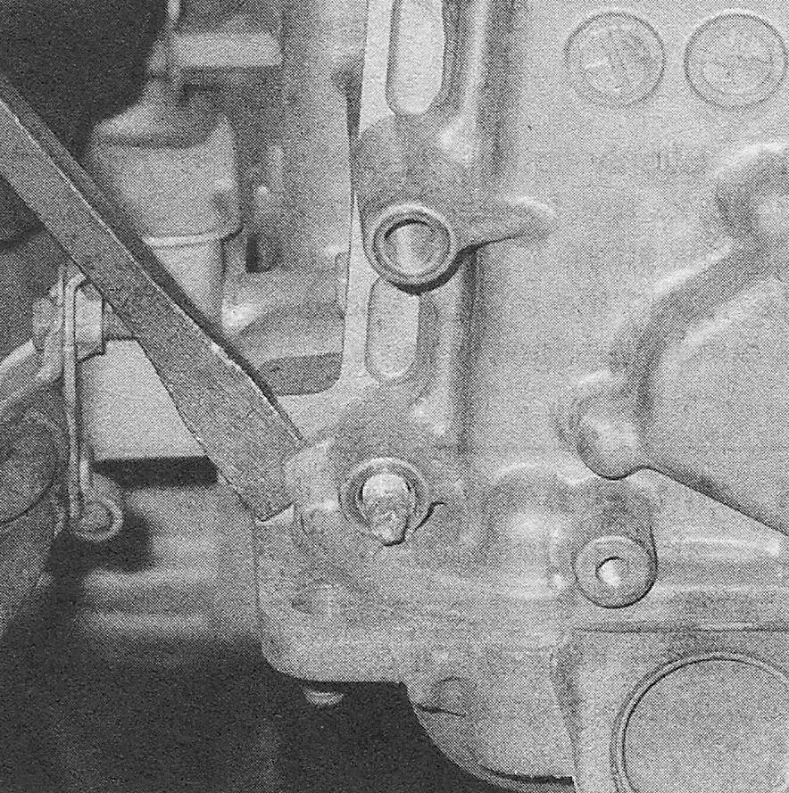
6. Remove the timing chain cover mounting fasteners and remove the timing chain cover. Note: There are three different sized bolts used on the timing chain cover (see illustration 7.40). There are only a few spots where you can safely pry the cover off without damaging it (see illustration). Do NOT pry the timing chain cover loose at any other spot or you will damage the sealing surface of the cover.
7.6 The timing chain cover can be pried loose at the lower corners and at the upper corners; prying anywhere else may damage the cover
7. After removing the timing chain cover, carefully pry out the old crankshaft seal with a screwdriver (see Crankshaft front oil seal — replacement). Make sure that you don’t scratch the seal bore. If you want to inspect or replace any oil pump parts, refer to Oil pump — removal, inspection and installation. Note: Keep track of the locations of all of the bolts. They are of different lengths and can’t be interchanged.
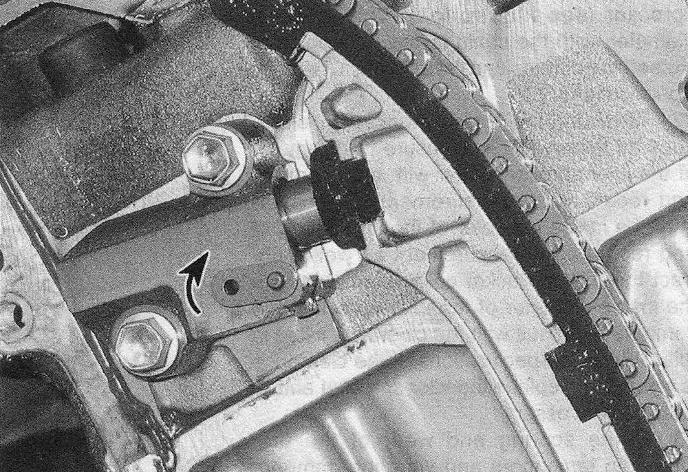
8. Verify that the piston in the No. 1 cylinder is near TDC on its compression stroke. If not, install the crankshaft pulley bolt, then rotate the crankshaft until the dot on the crankshaft position trigger wheel (the toothed wheel behind the lower crankshaft sprocket) is at the 11 o’clock position and is aligned with the rib on the engine block (see illustration). You can also temporarily install the front cover and the crankshaft pulley and set the pulley at the 0-degree mark. Verify that the timing marks on the camshaft timing sprockets are aligned with their corresponding marks on top of the front camshaft bearing caps (see illustrations). If the marks are not aligned, rotate the crankshaft another 360-degrees and recheck the marks.
7.8a Align the dot on the trigger wheel with the rib on the block — this should set the engine at TDC
7.8b the exhaust camshaft sprocket of the left (front) cylinder head with the engine at TDC
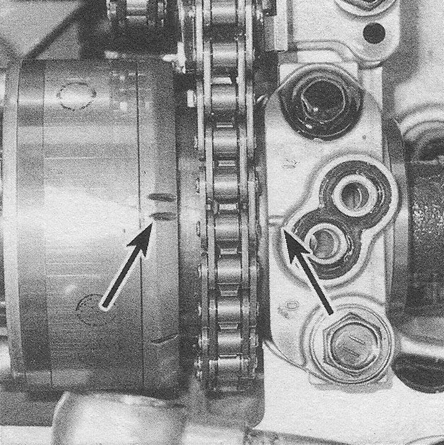
7.8c the intake camshaft sprocket of the left (front) cylinder head with the engine at TDC
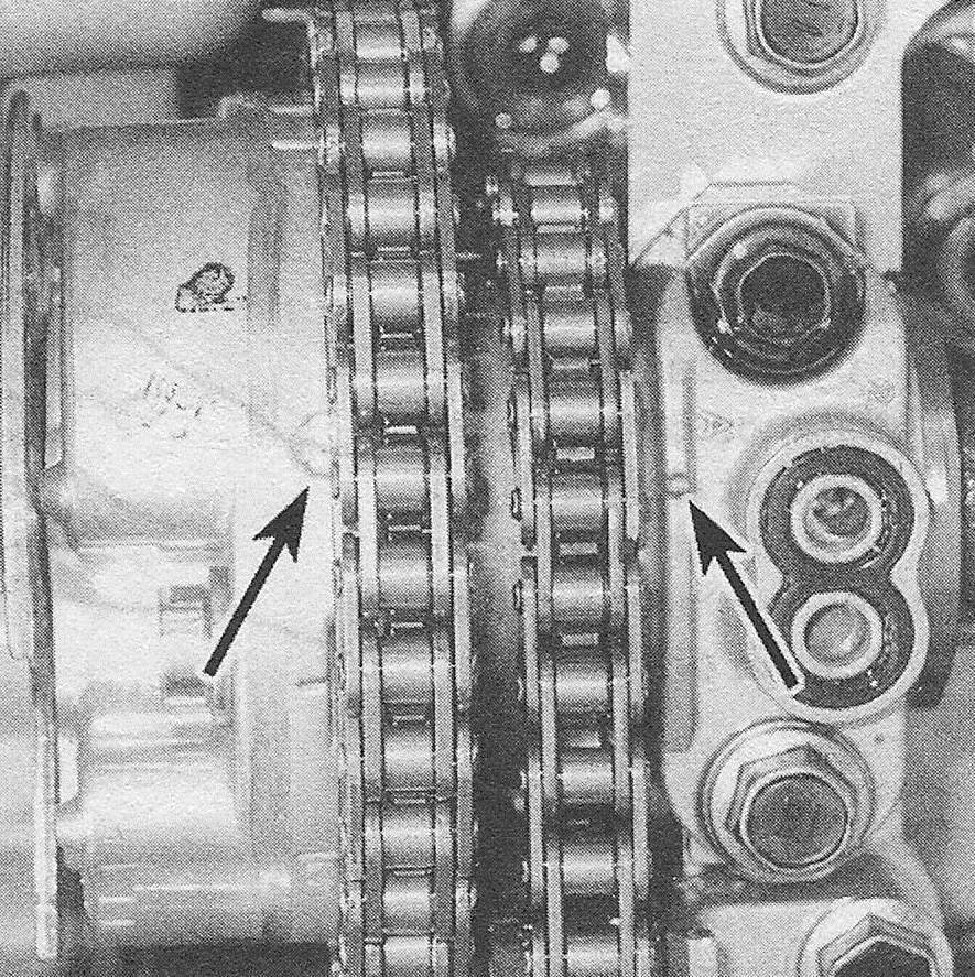
7.8d Alignment marks for the right (rear) camshaft sprockets
9. Turn the stopper plate on the No. 1 tensioner clockwise and push in the tensioner plunger (see illustration).
7.9 To lock the tensioner in the retracted position, rotate the stopper plate clockwise and push the plunger in, then rotate the stopper plate counterclockwise and insert a pin through the hole in the stopper plate and the tensioner body
Note: The No. 1 tensioner is the tensioner for the main timing chain. To lock the plunger in this position, turn the stopper plate counterclockwise and insert a drill or pin (2011 and earlier models: 0.138-inch diameter/2012 and later models: 0.050-inch diameter) through the holes in the stopper plate and the tensioner body. Remove the tensioner mounting bolts and the No. 1 tensioner.
10. Remove the chain tensioner slipper.
11. Using a 10 mm hex wrench, unscrew the idler sprocket shaft and remove the idler shaft, sprocket and collar. Note which side of the sprocket faces out.
12. Remove the chain vibration dampers. sprocket. Make sketches or take pictures. Remove the No. 1 (main) timing chain. Caution: While the No. 1 timing chain is removed, DO NOT ROTATE THE CRANKSHAFT!
14. Remove the crankshaft timing chain sprocket.
15. Compress chain tensioner No. 2 and insert a drill bit or punch (0.039-inch diameter) into the hole.
Note: Timing chain No. 2 and the No. 2 chain tensioner are on the right (rear) cylinder head. Timing chain No. 3 and the No. 3 tensioner are on the left (front) cylinder head.
16. Hold the hex on the exhaust camshaft with a wrench and unscrew the two bolts that secure the camshaft timing sprockets to the camshafts. Remove the sprockets and chain as an assembly. Keep the components in a resealable plastic bag to ensure that none of these components is mixed with the other timing chain set.
Caution: Don’t attempt to disassemble the adjustable intake sprocket assembly. If disassembled, it will have to be replaced.
17. Remove the chain tensioner No. 2 mounting bolt and remove chain tensioner No. 2. Store the tensioner in the plastic bag with the other No. 2 timing chain components.
18. To remove the No. 3 timing chain and tensioner, repeat these Steps. Again, store the components in a resealable plastic bag. Cau tion: While the timing chains are removed, DO NOT ROTATE THE CRANKSHAFT
Inspection
19. Inspect all parts of the timing chain assembly for wear and damage. Inspect the three timing chains for loose pins, cracks, and worn rollers and side plates. Inspect the sprockets for hook-shaped, chipped and/or broken teeth.
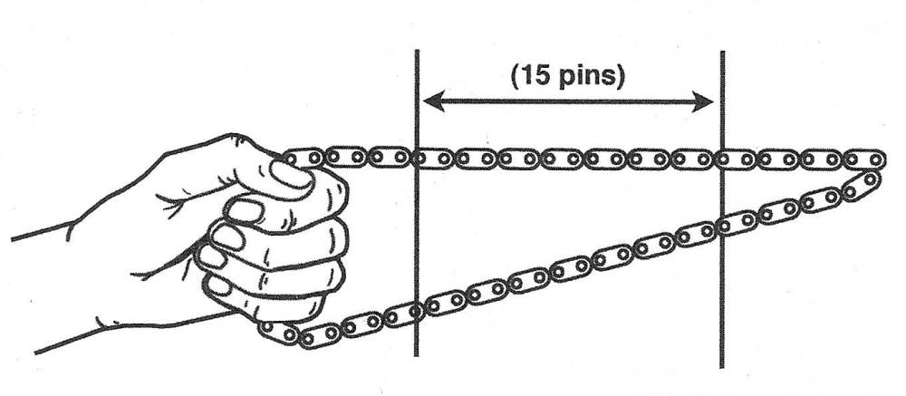
20. Inspect timing chain No. 1 for stretching. To measure timing chain, stretch, measure the distance between 15 pins at three or more places around the length of the chain (see illustration). Measure between the inside of the rollers and compare your measurements with the distance listed in this Chapter’s Specifications.
7.20 Measure timing chain stretch by measuring the distance between the closest points of 15 pins at three or more places around the length of the chain
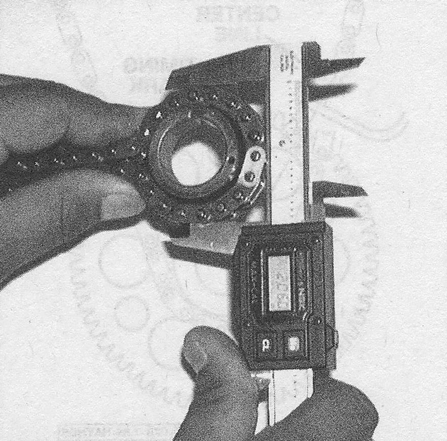
21. Measure the diameter of each timing chain sprocket and idler sprocket with the appropriate timing chain installed on the sprocket (see illustration). The sprocket diameter, with the chain in place, should not exceed the dimensions listed in this Chapter’s Specifications.
7.21 Wrap the chain around each of the timing chain sprockets and measure the diameter of the sprockets across the chain rollers. If the measurement is less than the minimum sprocket diameter, replace the chain and the timing sprockets
22. Measure the idler sprocket oil clearance as follows. First, measure the diameter of the idler sprocket collar with a micrometer and record your measurement. Then measure the inside diameter of the idler sprocket and record that measurement as well. Subtract the idler sprocket collar diameter from the inside diameter of the idler sprocket and compare the result with the clearance listed in this Chapter’s Specifications. If the clearance is excessive, replace the idler sprocket and/or collar, as necessary.
23. Some scoring and wear of the timing chain tensioners and vibration dampers is normal, but excessive wear will increase chain noise, accelerate chain and sprocket wear and could damage the engine if a chain jumps timing. Inspect chain tensioners No. 2 and 3, the timing chain tensioner slipper and the timing chain vibration dampers for excessive wear. If the measured chain wear for any of these components exceeds the depth listed in this Chapter’s Specifications, replace the component.
24. Check the chain tensioners for correct operation. On the No. 1 tensioner, raise the ratchet pawl and verify that the plunger moves smoothly in and out of the tensioner, then release the ratchet pawl and verify that it prevents the plunger from sliding back into the tensioner. Also verify that the plungers on the No. 2 and No. 3 tensioners move in and out smoothly.
Installation
Caution: Before starting the engine, carefully rotate the crankshaft by hand through at least two full revolutions (use a socket and breaker bar on the crankshaft pulley center bolt). If you feel any resistance, STOP! There is something wrong — most likely, valves are contacting the pistons. You must find the problem before proceeding.
25. Push in the tensioner plunger on chain tensioner No. 2 and insert a drill or punch (0.039-inch diameter) into the hole of the tensioner to lock the plunger in the retracted position. Install the tensioners and tighten the mounting bolts to the torque listed in this Chapter’s Specifications.
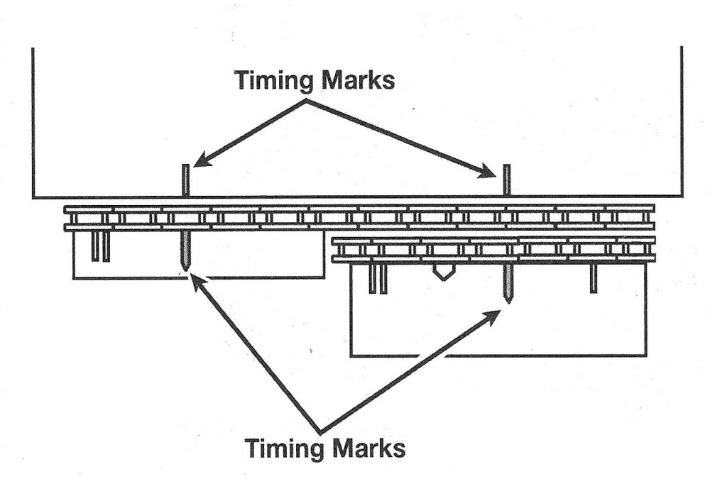
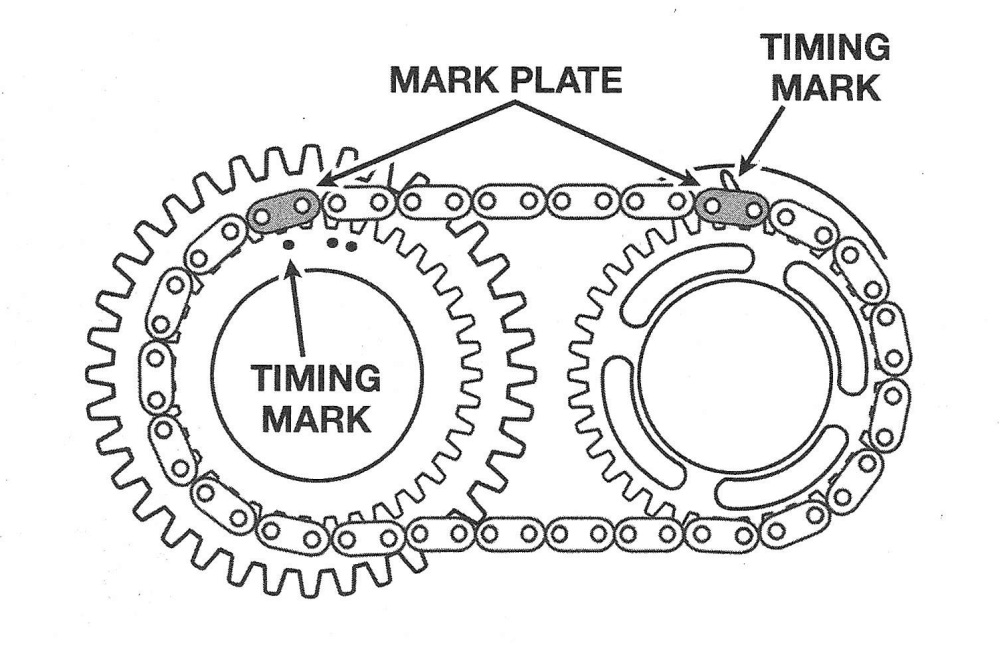
26. Install the No. 2 (right bank inner) timing chain on the camshaft sprockets. Make sure that the yellow mark links on the chain are aligned with the single timing dots or lines on the camshaft sprockets (see illustration).
7.26 The small No. 2 timing chain maintains the alignment of the intake and exhaust camshaft sprockets of the right (rear) cylinder head; set the yellow links on the single line and single dot of the camshaft sprockets
27. Align the yellow links on the No. 2 timing chain with the timing marks on the bearing caps and install timing chain No. 2 and the camshaft sprockets as an assembly. Install the two bolts that secure the timing sprockets to the camshafts. Immobilize the hex on the exhaust camshaft with an adjustable wrench and tighten these two bolts to the torque listed in this Chapter’s Specifications. Remove the drill or punch that was used to lock the tensioner plunger in its retracted position and verify that the plunger tensions the chain.
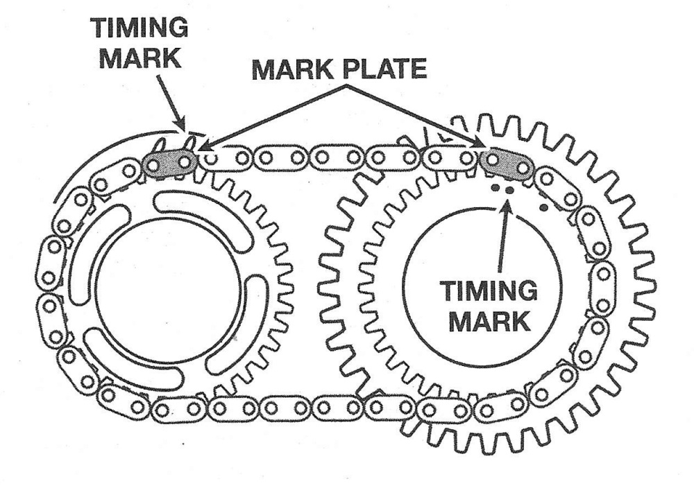
28. Install the other inner timing chain by repeating Steps 25 through 27. Align the yellow links with the double line or dot marks on the sprockets (see illustration). Also align its yellow links with the marks on the bearing caps.
7.28 Set the yellow links of the No. 3 timing chain of the left ( front) cylinder head on the double lines and double dots of the camshaft sprockets
29. Install the chain guides and tighten the bolts to the torque listed in this Chapter’s Specifications.
30. Install the crankshaft timing sprocket on the crankshaft. Be sure to align the timing sprocket keyway with the keys on the crankshaft.
31. Apply a light coat of engine oil to the bearing surface of the idler sprocket collar. Install the idler sprocket collar, sprocket and shaft. Make sure that the teeth on the idler sprocket are facing forward. Tighten the idler sprocket shaft to the torque listed in this Chapter’s Specifications.
32. Verify that the timing marks on the camshaft timing sprockets are aligned with their corresponding marks on top of the front camshaft bearing caps.
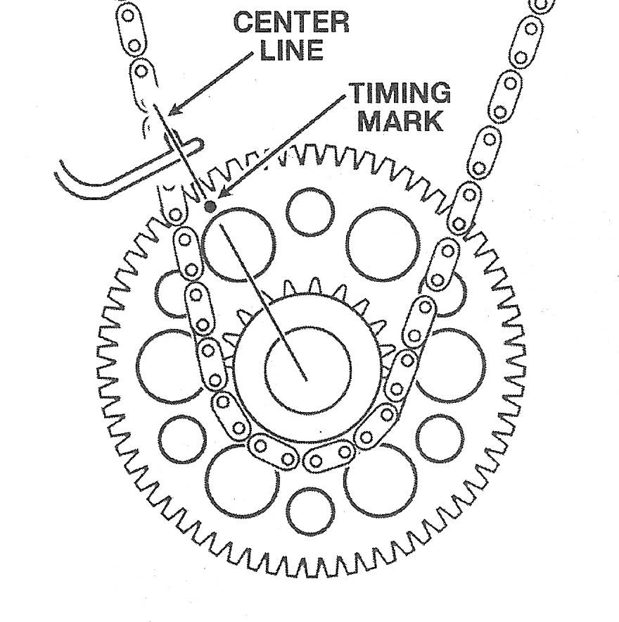
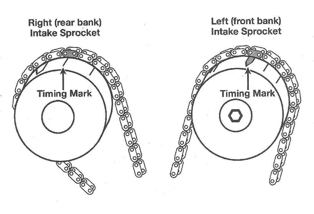
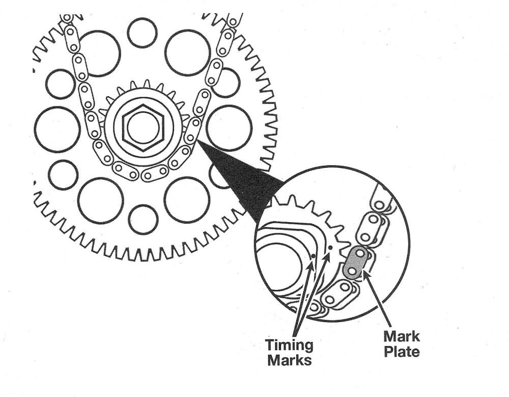
33. Install the long timing chain (No. 1) on the camshaft timing sprockets and on the idler sprocket. Turn the camshaft sprockets to remove the slack in the upper part of the chain, then install the chain over the crankshaft sprocket. Make sure that the yellow link is aligned with the timing dot on the crankshaft timing sprocket (it’s near the 3 o’clock position) and that the orange links are aligned with the timing marks on the intake camshaft sprockets (see. illustrations). There is a dot on the crankshaft position trigger wheel (the toothed wheel behind the lower crankshaft sprocket) that must be at the 11 o’clock position and aligned with the rib on the engine block (see illustration 7.8a).
7.33a the orange links of the No. 1 (main) timing chain must align with the correct marks on each intake sprocket — the rear single line on the right (rear bank) head and the large arrowhead on the left (front bank) head
7.33b the lower yellow link of the No. 1 timing chain aligns with the dots on the crankshaft at about the two o’clock position
34. Turn the stopper plate on the No. 1 tensioner clockwise and push in the tensioner plunger. To lock the plunger in this position, turn the stopper plate counterclockwise and insert a drill or punch (0.138-inch diameter) through the holes in the stopper plate and the tensioner. Install the tensioner and tighten the tensioner mounting bolts to the torque listed in this Chapter’s Specifications. Remove the drill or punch that you inserted into chain tensioner No. 1 and verify that it tensions timing chain No. 1. Caution: Carefully rotate the crankshaft by hand through at least two full revolutions (use a socket and breaker bar on the crankshaft pulley center bolt). If you feel any resistance, STOP! There is something wrong — most likely, valves are contacting the pistons. You must find the problem before proceeding.
35. Remove all old RTV sealant from the gasket mating surfaces of the timing chain cover and from the front of the cylinder heads and engine block.
36. Install a new crankshaft oil seal in the timing chain cover (see Crankshaft front oil seal — replacement).
37. Install a new 0-ring on the left cylinder head.
38. Apply gray RTV sealant on the timing chain cover in all areas where the cover seals to the engine block and oil pan. These beads should be about 1/8 to 3/16-inch (3 to 4.5 mm) wide. Caution: Once you have installed the sealant on the engine and timing chain cover you have three minutes to install the cover. If you take longer than that, the sealant might not set up properly, so you’ll have to remove the sealant and re-apply it. Be sure to get sealant into the corners where the oil pan meets the engine block and avoid getting any on the 0-rings.
39. Rotate the flats on the oil drive rotor to align it with the square part of the crankshaft timing sprocket and slide the timing chain cover into place.
40. Install all of the cover bolts in the same locations they were removed from, tightening them as you go.
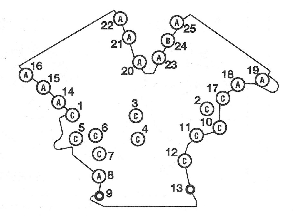
Caution: Do not put long bolts in short holes or vice versa. Tighten all of the bolts in the proper sequence to the torque listed in this Chapter’s Specifications (see illustration).
7.40 Timing chain cover bolt length and tightening sequence
A Bolt A 0.98-inches (25 mm) length
B Bolt B 2.17-inches (55 mm) length
C Bolt C 1.57-inches (40 mm) length
41. Install and tighten the four oil pan bolts that go into the timing chain cover.
42. The remainder of installation is the reverse of removal.
43. Install the engine/transaxle assembly.
44. Refill the engine with oil and coolant (see Tune-up and routine maintenance).
45. Reconnect the cable to the negative terminal of the battery (see Engine electrical systems).
46. Start the engine and check for leaks